Cirkit Designer Logo
Cirkit Designer
Your all-in-one circuit design IDE
Home / 
Component Documentation

How to Use 3.3V Regulator: Examples, Pinouts, and Specs

Image of 3.3V Regulator
Cirkit Designer LogoDesign with 3.3V Regulator in Cirkit Designer

Introduction

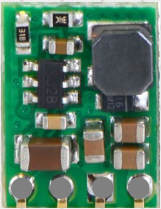
The Pololu D36V6F5 is a compact and efficient 3.3V voltage regulator designed to provide a stable 3.3V output from a higher input voltage source. This regulator is ideal for powering low-voltage devices such as microcontrollers, sensors, and communication modules. Its small size and high efficiency make it suitable for a wide range of applications, including embedded systems, robotics, and portable electronics.

Explore Projects Built with 3.3V Regulator

Use Cirkit Designer to design, explore, and prototype these projects online. Some projects support real-time simulation. Click "Open Project" to start designing instantly!
Battery-Powered 18650 Li-ion Charger with USB Output and Adjustable Voltage Regulator
Image of Breadboard: A project utilizing 3.3V Regulator in a practical application
This circuit is a battery management and power supply system that uses three 3.7V batteries connected to a 3S 10A Li-ion 18650 Charger Protection Board Module for balanced charging and protection. The system includes a TP4056 Battery Charging Protection Module for additional charging safety, a Step Up Boost Power Converter to regulate and boost the voltage, and a USB regulator to provide a stable 5V output, controlled by a push switch.
Cirkit Designer LogoOpen Project in Cirkit Designer
Battery-Powered LED Control Circuit with Potentiometer and Transistors
Image of STROBE LIGHTS: A project utilizing 3.3V Regulator in a practical application
This circuit is a regulated power supply with a 12V battery input, a 7805 voltage regulator providing a 5V output, and a potentiometer for adjustable voltage control. It includes transistors and resistors for current regulation and an LED indicator to show the operational status.
Cirkit Designer LogoOpen Project in Cirkit Designer
Adjustable LM317 Voltage Regulator with ESP32 Control
Image of Reciever: A project utilizing 3.3V Regulator in a practical application
This circuit is a variable voltage power supply featuring an LM317 voltage regulator for adjustable output. It includes an ESP32 microcontroller powered through the regulator, with input and output voltage stabilization provided by tantalum capacitors. A rotary potentiometer is used to set the desired voltage level.
Cirkit Designer LogoOpen Project in Cirkit Designer
LM317 Voltage Regulator Circuit for Adjustable Power Supply with Transformer and Diodes
Image of 12V BULB LIGHT DIMMER CIRCUIT: A project utilizing 3.3V Regulator in a practical application
This circuit is a regulated power supply that converts AC voltage to a stable DC voltage. It uses a transformer to step down the AC voltage, diodes for rectification, an electrolytic capacitor for smoothing, and an LM317 voltage regulator to provide a stable output voltage, which is adjustable via a potentiometer. The output powers a bulb.
Cirkit Designer LogoOpen Project in Cirkit Designer

Explore Projects Built with 3.3V Regulator

Use Cirkit Designer to design, explore, and prototype these projects online. Some projects support real-time simulation. Click "Open Project" to start designing instantly!
Image of Breadboard: A project utilizing 3.3V Regulator in a practical application
Battery-Powered 18650 Li-ion Charger with USB Output and Adjustable Voltage Regulator
This circuit is a battery management and power supply system that uses three 3.7V batteries connected to a 3S 10A Li-ion 18650 Charger Protection Board Module for balanced charging and protection. The system includes a TP4056 Battery Charging Protection Module for additional charging safety, a Step Up Boost Power Converter to regulate and boost the voltage, and a USB regulator to provide a stable 5V output, controlled by a push switch.
Cirkit Designer LogoOpen Project in Cirkit Designer
Image of STROBE LIGHTS: A project utilizing 3.3V Regulator in a practical application
Battery-Powered LED Control Circuit with Potentiometer and Transistors
This circuit is a regulated power supply with a 12V battery input, a 7805 voltage regulator providing a 5V output, and a potentiometer for adjustable voltage control. It includes transistors and resistors for current regulation and an LED indicator to show the operational status.
Cirkit Designer LogoOpen Project in Cirkit Designer
Image of Reciever: A project utilizing 3.3V Regulator in a practical application
Adjustable LM317 Voltage Regulator with ESP32 Control
This circuit is a variable voltage power supply featuring an LM317 voltage regulator for adjustable output. It includes an ESP32 microcontroller powered through the regulator, with input and output voltage stabilization provided by tantalum capacitors. A rotary potentiometer is used to set the desired voltage level.
Cirkit Designer LogoOpen Project in Cirkit Designer
Image of 12V BULB LIGHT DIMMER CIRCUIT: A project utilizing 3.3V Regulator in a practical application
LM317 Voltage Regulator Circuit for Adjustable Power Supply with Transformer and Diodes
This circuit is a regulated power supply that converts AC voltage to a stable DC voltage. It uses a transformer to step down the AC voltage, diodes for rectification, an electrolytic capacitor for smoothing, and an LM317 voltage regulator to provide a stable output voltage, which is adjustable via a potentiometer. The output powers a bulb.
Cirkit Designer LogoOpen Project in Cirkit Designer

Common Applications

  • Powering microcontrollers (e.g., Arduino, ESP32, STM32)
  • Supplying stable voltage to sensors and modules
  • Battery-powered devices
  • Robotics and automation systems
  • Low-power IoT devices

Technical Specifications

The following table outlines the key technical details of the Pololu D36V6F5 3.3V regulator:

Parameter Value
Input Voltage Range 4.5V to 50V
Output Voltage 3.3V
Maximum Output Current 600 mA
Efficiency Up to 90% (depending on input voltage)
Quiescent Current < 1 mA
Operating Temperature -40°C to +85°C
Dimensions 0.4" × 0.5" × 0.1" (10 × 13 × 3 mm)

Pin Configuration

The Pololu D36V6F5 regulator has three pins for easy integration into circuits. The pinout is as follows:

Pin Name Description
1 VIN Input voltage (4.5V to 50V)
2 GND Ground connection
3 VOUT Regulated 3.3V output

Usage Instructions

How to Use the Component in a Circuit

  1. Connect the Input Voltage (VIN):

    • Attach the positive terminal of your power source (4.5V to 50V) to the VIN pin.
    • Ensure the input voltage is within the specified range to avoid damaging the regulator.
  2. Connect the Ground (GND):

    • Connect the GND pin to the ground of your circuit.
  3. Connect the Output Voltage (VOUT):

    • Use the VOUT pin to power your 3.3V devices. Ensure the total current draw does not exceed 600 mA.
  4. Add Decoupling Capacitors (Optional):

    • For improved stability, you can add a 10 µF capacitor between VIN and GND and another 10 µF capacitor between VOUT and GND.

Important Considerations and Best Practices

  • Heat Dissipation:
    The regulator is efficient, but if you are operating near the maximum current limit, ensure proper ventilation or heat sinking to prevent overheating.

  • Input Voltage Range:
    Always verify that the input voltage is within the 4.5V to 50V range. Exceeding this range can permanently damage the regulator.

  • Polarity Protection:
    The regulator does not have built-in reverse polarity protection. Double-check your connections to avoid damage.

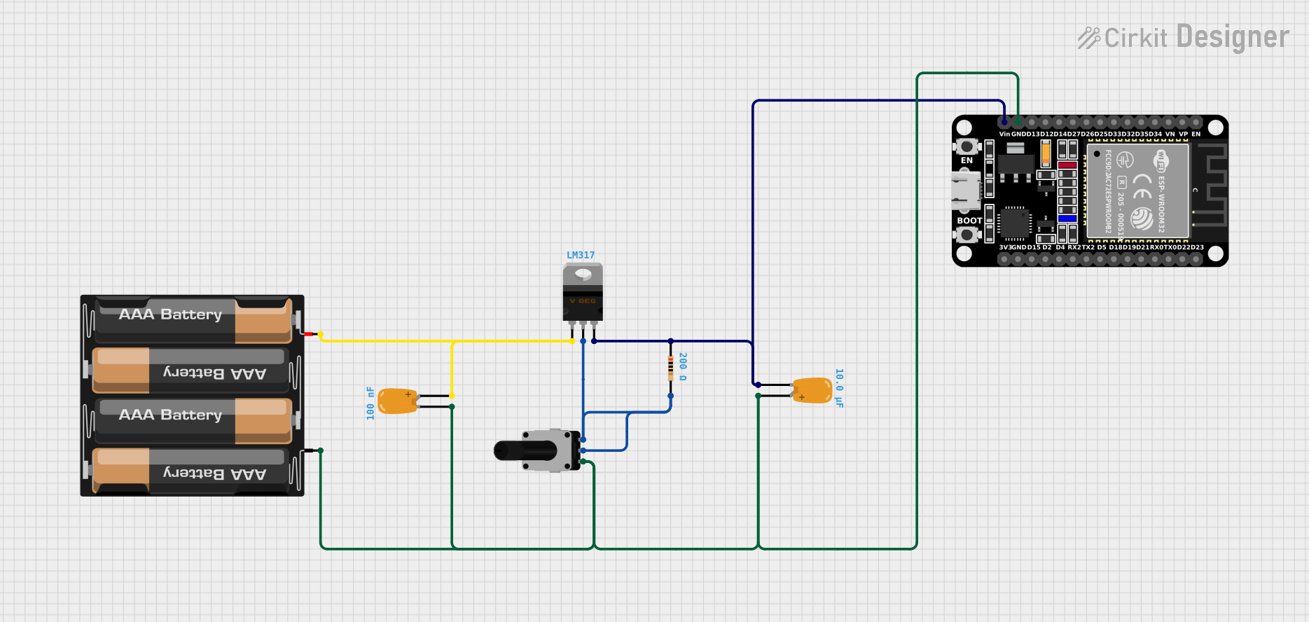
Example: Using the 3.3V Regulator with an Arduino UNO

The Pololu D36V6F5 can be used to power an Arduino UNO by stepping down a higher voltage source to 3.3V. Below is an example of how to connect the regulator:

  1. Connect a 9V battery to the VIN pin of the regulator.
  2. Connect the GND pin of the regulator to the ground of the Arduino UNO.
  3. Connect the VOUT pin of the regulator to the 3.3V pin of the Arduino UNO.

Sample Arduino Code

If you are powering sensors or modules with the 3.3V regulator, you can use the following code to read data from a 3.3V sensor (e.g., a temperature sensor):

// Example code to read data from a 3.3V temperature sensor
const int sensorPin = A0; // Analog pin connected to the sensor output

void setup() {
  Serial.begin(9600); // Initialize serial communication
  pinMode(sensorPin, INPUT); // Set the sensor pin as input
}

void loop() {
  int sensorValue = analogRead(sensorPin); // Read the sensor value
  float voltage = sensorValue * (3.3 / 1023.0); // Convert to voltage
  Serial.print("Sensor Voltage: ");
  Serial.print(voltage);
  Serial.println(" V");
  delay(1000); // Wait for 1 second before the next reading
}

Troubleshooting and FAQs

Common Issues and Solutions

  1. No Output Voltage:

    • Cause: Input voltage is below 4.5V or connections are incorrect.
    • Solution: Verify the input voltage and ensure proper wiring.
  2. Overheating:

    • Cause: Excessive current draw or insufficient ventilation.
    • Solution: Reduce the load current or improve heat dissipation.
  3. Fluctuating Output Voltage:

    • Cause: Insufficient decoupling capacitors or unstable input voltage.
    • Solution: Add 10 µF capacitors between VIN and GND, and VOUT and GND.
  4. Regulator Damage:

    • Cause: Input voltage exceeded 50V or reverse polarity connection.
    • Solution: Replace the regulator and ensure proper voltage and polarity.

FAQs

Q: Can I use this regulator to power a 5V device?
A: No, this regulator is designed to output a fixed 3.3V. For 5V devices, use a 5V regulator.

Q: Is the regulator suitable for battery-powered applications?
A: Yes, its low quiescent current (< 1 mA) makes it ideal for battery-powered devices.

Q: Can I use this regulator with a 12V power supply?
A: Yes, as long as the input voltage is between 4.5V and 50V, the regulator will step it down to 3.3V.

Q: Does the regulator have short-circuit protection?
A: No, the Pololu D36V6F5 does not include short-circuit protection. Avoid shorting the output to ground.