
How to Use Raspberry Pi B rev1: Examples, Pinouts, and Specs
 Design with Raspberry Pi B rev1 in Cirkit Designer
Introduction
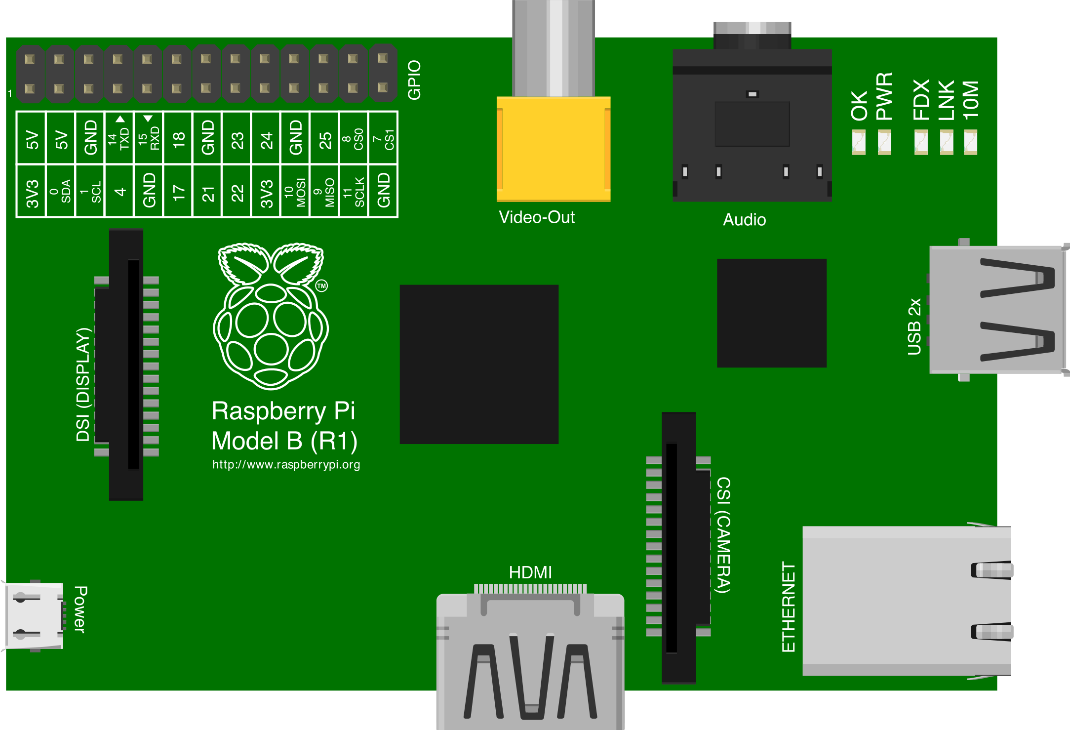
The Raspberry Pi Model B Revision 1, manufactured by the Raspberry Pi Foundation, is a compact and affordable single-board computer designed for educational purposes, prototyping, and hobbyist projects. It features a 700 MHz ARM11 processor, 512 MB of RAM, and a set of GPIO (General Purpose Input/Output) pins for interfacing with external hardware. This versatile device is ideal for learning programming, building IoT (Internet of Things) projects, and experimenting with electronics.
Explore Projects Built with Raspberry Pi B rev1
 Open Project in Cirkit Designer
 Open Project in Cirkit Designer
 Open Project in Cirkit Designer
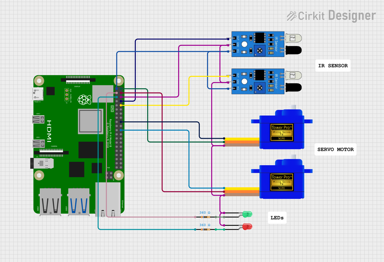 Open Project in Cirkit Designer
Explore Projects Built with Raspberry Pi B rev1
Open Project in Cirkit DesignerOpen Project in Cirkit DesignerOpen Project in Cirkit DesignerOpen Project in Cirkit DesignerCommon Applications and Use Cases
- Educational Projects: Teaching programming languages like Python, Scratch, and C.
- IoT Development: Building smart home devices and automation systems.
- Media Centers: Setting up lightweight media servers using software like Kodi.
- Prototyping: Interfacing with sensors, motors, and other peripherals for robotics and electronics projects.
- Networking: Acting as a lightweight server or network monitoring tool.
Technical Specifications
Key Technical Details
| Specification | Details |
|---|---|
| Processor | 700 MHz ARM11 |
| RAM | 512 MB |
| Storage | SD card slot for booting and storage |
| USB Ports | 2 x USB 2.0 |
| Ethernet | 10/100 Mbps Ethernet port |
| Video Output | HDMI and RCA composite video |
| Audio Output | 3.5 mm audio jack and HDMI |
| GPIO Pins | 26-pin header (17 GPIO pins available) |
| Power Supply | 5V micro-USB, 700 mA minimum |
| Dimensions | 85.6 mm x 56.5 mm x 21 mm |
| Weight | 45 g |
GPIO Pin Configuration
The Raspberry Pi Model B Revision 1 features a 26-pin GPIO header. Below is the pinout:
| Pin Number | Pin Name | Description |
|---|---|---|
| 1 | 3.3V | Power supply (3.3V) |
| 2 | 5V | Power supply (5V) |
| 3 | GPIO 0 (SDA) | I2C Data |
| 4 | 5V | Power supply (5V) |
| 5 | GPIO 1 (SCL) | I2C Clock |
| 6 | Ground | Ground |
| 7 | GPIO 4 | General-purpose I/O |
| 8 | GPIO 14 (TXD) | UART Transmit |
| 9 | Ground | Ground |
| 10 | GPIO 15 (RXD) | UART Receive |
| 11 | GPIO 17 | General-purpose I/O |
| 12 | GPIO 18 | PWM Output |
| 13 | GPIO 21 | General-purpose I/O |
| 14 | Ground | Ground |
| 15 | GPIO 22 | General-purpose I/O |
| 16 | GPIO 23 | General-purpose I/O |
| 17 | 3.3V | Power supply (3.3V) |
| 18 | GPIO 24 | General-purpose I/O |
| 19 | GPIO 10 (MOSI) | SPI Master Out, Slave In |
| 20 | Ground | Ground |
| 21 | GPIO 9 (MISO) | SPI Master In, Slave Out |
| 22 | GPIO 25 | General-purpose I/O |
| 23 | GPIO 11 (SCLK) | SPI Clock |
| 24 | GPIO 8 (CE0) | SPI Chip Enable 0 |
| 25 | Ground | Ground |
| 26 | GPIO 7 (CE1) | SPI Chip Enable 1 |
Usage Instructions
How to Use the Raspberry Pi Model B Revision 1
Powering the Device:
- Use a 5V micro-USB power supply capable of delivering at least 700 mA.
- Ensure the power supply is stable to avoid unexpected shutdowns.
Setting Up the Operating System:
- Download a compatible OS (e.g., Raspbian) from the Raspberry Pi Foundation's website.
- Flash the OS image onto an SD card using tools like Balena Etcher.
- Insert the SD card into the Raspberry Pi's SD card slot.
Connecting Peripherals:
- Attach a USB keyboard and mouse to the USB ports.
- Connect a monitor via HDMI or RCA composite video.
- Optionally, connect the Ethernet cable for network access.
Using GPIO Pins:
- Use the GPIO pins to interface with external components like LEDs, sensors, and motors.
- Be cautious about voltage levels; GPIO pins operate at 3.3V and are not 5V tolerant.
Example: Blinking an LED with GPIO
Below is an example of how to blink an LED connected to GPIO 17 using Python:
Import the GPIO library
import RPi.GPIO as GPIO import time
Set up GPIO mode
GPIO.setmode(GPIO.BCM) # Use Broadcom pin numbering GPIO.setup(17, GPIO.OUT) # Set GPIO 17 as an output pin
try: while True: GPIO.output(17, GPIO.HIGH) # Turn LED on time.sleep(1) # Wait for 1 second GPIO.output(17, GPIO.LOW) # Turn LED off time.sleep(1) # Wait for 1 second except KeyboardInterrupt: # Clean up GPIO settings on exit GPIO.cleanup()
Important Considerations and Best Practices
- Always shut down the Raspberry Pi properly to avoid corrupting the SD card.
- Use a heat sink if the device is used for extended periods or under heavy load.
- Avoid connecting GPIO pins directly to high-voltage sources to prevent damage.
- Use pull-up or pull-down resistors when working with GPIO inputs to ensure stable signals.
Troubleshooting and FAQs
Common Issues and Solutions
The Raspberry Pi does not boot:
- Ensure the SD card is properly inserted and contains a valid OS image.
- Check the power supply for sufficient voltage and current.
No display on the monitor:
- Verify the HDMI cable is securely connected.
- Check if the monitor is set to the correct input source.
- Edit the
config.txtfile on the SD card to force HDMI output if necessary.
GPIO pins not working:
- Ensure the correct pin numbering mode (BCM or BOARD) is used in your code.
- Check for loose connections or damaged components.
Overheating:
- Use a heat sink or fan to improve cooling.
- Avoid placing the Raspberry Pi in enclosed spaces without ventilation.
FAQs
Can I power the Raspberry Pi via GPIO pins? Yes, you can power the Raspberry Pi by supplying 5V to the 5V GPIO pin, but this bypasses the onboard voltage regulation and protection circuits. Use caution.
What is the maximum current the GPIO pins can handle? Each GPIO pin can source/sink a maximum of 16 mA, with a total limit of 50 mA across all GPIO pins.
Can I use the Raspberry Pi Model B Revision 1 for modern applications? While it is suitable for basic tasks, its limited processing power and memory may not handle resource-intensive applications effectively.
This concludes the documentation for the Raspberry Pi Model B Revision 1.