How to Use Helical Antenna (Spring Coil Antenna): Examples, Pinouts, and Specs
Introduction
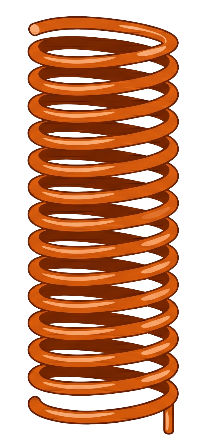
A helical antenna, also known as a spring coil antenna, is a type of antenna made from a wire wound into a helical (spiral) shape. It is widely used for transmitting and receiving radio waves, particularly in applications requiring circular polarization. The helical design allows for compact size and efficient performance, making it ideal for use in communication systems such as GPS, Wi-Fi, RFID, and IoT devices.
Explore Projects Built with Helical Antenna (Spring Coil Antenna)

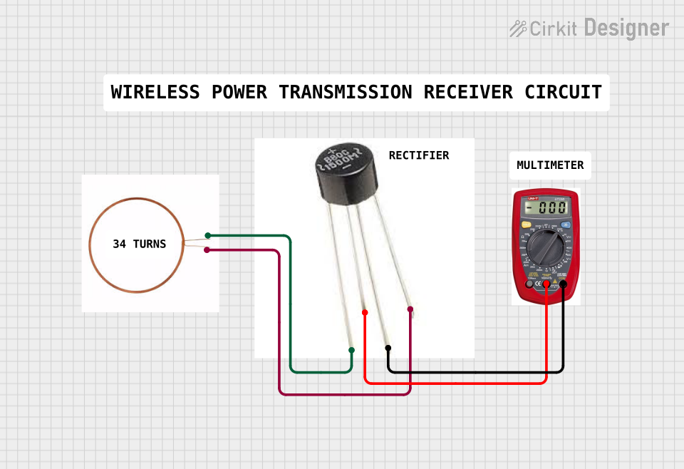


Explore Projects Built with Helical Antenna (Spring Coil Antenna)
Common Applications and Use Cases
- Wireless Communication Systems: Used in devices like Wi-Fi routers and Bluetooth modules.
- GPS Systems: Provides circular polarization for accurate signal reception.
- IoT Devices: Compact size makes it suitable for embedded systems.
- RFID Systems: Used in tags and readers for efficient signal transmission.
- Satellite Communication: Supports circularly polarized signals for space communication.
Technical Specifications
Below are the key technical details for a typical helical antenna:
| Parameter | Value |
|---|---|
| Frequency Range | 300 MHz to 5 GHz (varies by design) |
| Polarization | Circular or Linear |
| Impedance | 50 Ω |
| Gain | 3 dBi to 15 dBi (depends on size and turns) |
| VSWR (Voltage Standing Wave Ratio) | ≤ 2:1 |
| Material | Copper or other conductive metals |
| Dimensions | Varies (e.g., 10 mm to 50 mm height) |
| Operating Temperature | -40°C to +85°C |
Pin Configuration and Descriptions
Helical antennas typically have two connection points: the feed point and the ground. These are described below:
| Pin | Description |
|---|---|
| Feed Point | Connects to the RF signal source or transmitter. |
| Ground | Connects to the ground plane or circuit ground. |
Usage Instructions
How to Use the Component in a Circuit
- Determine the Operating Frequency: Ensure the antenna is designed for the frequency range of your application (e.g., 2.4 GHz for Wi-Fi).
- Connect the Feed Point: Solder the feed point of the antenna to the RF output of your circuit or module.
- Connect the Ground: Attach the ground pin to the circuit's ground plane for proper operation.
- Position the Antenna: Orient the antenna vertically or in the desired direction for optimal signal reception or transmission.
- Use a Ground Plane: For best performance, use a ground plane beneath the antenna to enhance signal strength and stability.
Important Considerations and Best Practices
- Antenna Placement: Avoid placing the antenna near metal objects or enclosures, as this can degrade performance.
- Tuning: If necessary, adjust the number of turns or the spacing of the helix to fine-tune the antenna for your desired frequency.
- Impedance Matching: Use a matching network if the antenna impedance does not match the circuit impedance (typically 50 Ω).
- Testing: Use an SWR meter or network analyzer to verify the antenna's performance.
Example: Using a Helical Antenna with Arduino UNO
Below is an example of connecting a helical antenna to an RF module (e.g., NRF24L01) and controlling it with an Arduino UNO:
/*
  Example: Using a Helical Antenna with NRF24L01 and Arduino UNO
  This code demonstrates basic communication using an RF module with a helical antenna.
  Ensure the antenna is properly connected to the RF module's antenna port.
*/

#include <SPI.h>
#include <nRF24L01.h>
#include <RF24.h>

// Define the CE and CSN pins for the NRF24L01 module
#define CE_PIN 9
#define CSN_PIN 10

// Create an RF24 object
RF24 radio(CE_PIN, CSN_PIN);

// Define the address for communication
const byte address[6] = "00001";

void setup() {
  Serial.begin(9600); // Initialize serial communication
  radio.begin();      // Initialize the RF module
  radio.openWritingPipe(address); // Set the address for transmission
  radio.setPALevel(RF24_PA_HIGH); // Set power level to high
  radio.stopListening();          // Set module to transmit mode
}

void loop() {
  const char text[] = "Hello, World!"; // Message to send
  bool success = radio.write(&text, sizeof(text)); // Send the message

  if (success) {
    Serial.println("Message sent successfully!");
  } else {
    Serial.println("Message failed to send.");
  }

  delay(1000); // Wait 1 second before sending the next message
}
Troubleshooting and FAQs
Common Issues Users Might Face
Poor Signal Strength:
- Cause: Antenna placement near metal objects or inside enclosures.
- Solution: Relocate the antenna to an open area and ensure proper orientation.
High VSWR:
- Cause: Impedance mismatch or incorrect antenna tuning.
- Solution: Use a matching network or adjust the antenna's dimensions.
Interference:
- Cause: Nearby devices operating on the same frequency.
- Solution: Change the operating frequency or reduce interference sources.
No Signal Reception:
- Cause: Incorrect connections or damaged antenna.
- Solution: Verify connections and inspect the antenna for physical damage.
Solutions and Tips for Troubleshooting
- Use a network analyzer to measure the antenna's performance and ensure it operates within the desired frequency range.
- Ensure the ground plane is properly connected and large enough to support the antenna's operation.
- Test the antenna in different environments to identify and mitigate interference sources.
By following this documentation, users can effectively integrate and troubleshoot a helical antenna in their projects.