How to Use LM2596 Buck Converter (5V Regulator): Examples, Pinouts, and Specs
Introduction
The LM2596 Buck Converter is a step-down voltage regulator designed to efficiently convert higher input voltages into a stable 5V output. Manufactured as part of the LM2596S module series, this component is widely used in power supply applications due to its high efficiency, adjustable output voltage, and built-in thermal protection. It is ideal for powering microcontrollers, sensors, and other low-voltage devices from higher voltage sources such as batteries or adapters.
Explore Projects Built with LM2596 Buck Converter (5V Regulator)


Explore Projects Built with LM2596 Buck Converter (5V Regulator)
Common Applications and Use Cases
- Powering microcontrollers (e.g., Arduino, Raspberry Pi)
- Battery-powered devices
- DC-DC voltage regulation in embedded systems
- LED drivers
- Robotics and IoT projects
Technical Specifications
The LM2596 Buck Converter is designed to provide reliable and efficient voltage regulation. Below are its key technical details:
Key Technical Details
| Parameter | Value |
|---|---|
| Input Voltage Range | 4.5V to 40V |
| Output Voltage | Adjustable (default: 5V) |
| Output Current | Up to 3A (with proper heat dissipation) |
| Efficiency | Up to 92% |
| Switching Frequency | 150 kHz |
| Operating Temperature | -40°C to +125°C |
| Thermal Shutdown | Yes |
| Short-Circuit Protection | Yes |
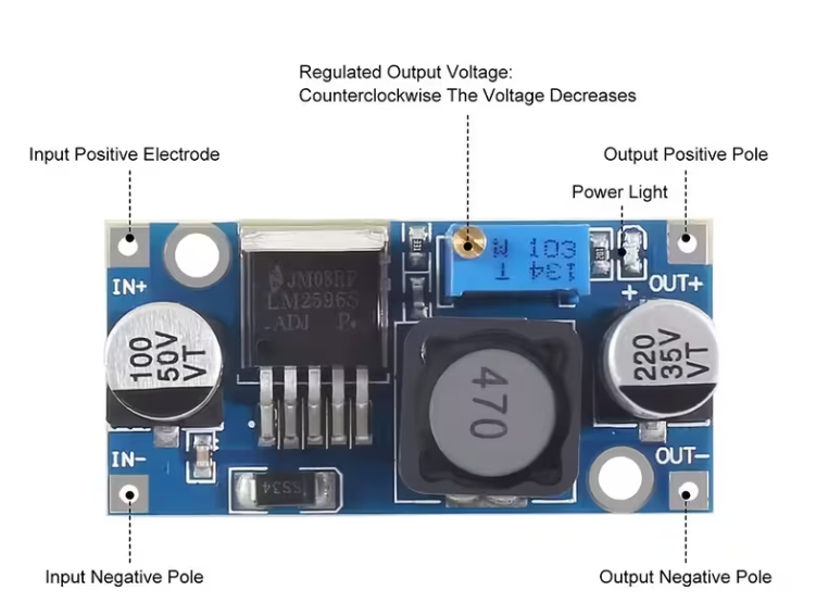
Pin Configuration and Descriptions
The LM2596 module typically has the following pin configuration:
| Pin Name | Description |
|---|---|
| VIN | Input voltage pin. Connect to the positive terminal of the input power source. |
| GND | Ground pin. Connect to the negative terminal of the input power source. |
| VOUT | Regulated output voltage pin. Connect to the load or circuit requiring 5V. |
Usage Instructions
The LM2596 Buck Converter is straightforward to use in a circuit. Follow the steps below to integrate it into your project:
How to Use the LM2596 in a Circuit
Connect the Input Voltage (VIN):
- Attach the positive terminal of your power source (e.g., battery or adapter) to the VIN pin.
- Connect the negative terminal of the power source to the GND pin.
Connect the Output Voltage (VOUT):
- Connect the VOUT pin to the positive terminal of your load or circuit.
- Ensure the load's ground is connected to the GND pin.
Adjust the Output Voltage (if needed):
- Use the onboard potentiometer to adjust the output voltage. Turn the potentiometer clockwise to increase the voltage and counterclockwise to decrease it.
- Use a multimeter to measure the output voltage while adjusting.
Verify Connections:
- Double-check all connections to ensure proper polarity and avoid short circuits.
Power On:
- Turn on the input power source and verify the output voltage with a multimeter.
Important Considerations and Best Practices
- Heat Dissipation: The LM2596 can handle up to 3A of current, but proper heat dissipation (e.g., a heatsink) is required for high-current applications.
- Input Voltage: Ensure the input voltage is at least 1.5V higher than the desired output voltage for proper regulation.
- Capacitors: Use appropriate input and output capacitors (e.g., 100 µF electrolytic capacitors) to stabilize the voltage and reduce noise.
- Polarity: Always connect the input and output terminals with the correct polarity to avoid damage.
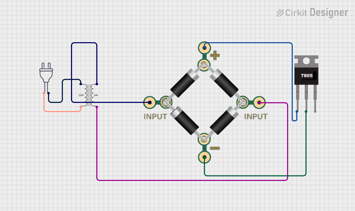
Example: Using LM2596 with Arduino UNO
The LM2596 can be used to power an Arduino UNO from a 12V power source. Below is an example circuit and Arduino code:
Circuit Connections
- Connect the 12V power source to the VIN and GND pins of the LM2596.
- Adjust the LM2596 output to 5V using a multimeter and the potentiometer.
- Connect the VOUT pin to the Arduino UNO's 5V pin and GND to GND.
Arduino Code Example
// Example code to blink an LED using Arduino UNO powered by LM2596
// Ensure the LM2596 output is set to 5V before connecting to the Arduino

const int ledPin = 13; // Built-in LED pin on Arduino UNO

void setup() {
  pinMode(ledPin, OUTPUT); // Set LED pin as output
}

void loop() {
  digitalWrite(ledPin, HIGH); // Turn the LED on
  delay(1000);               // Wait for 1 second
  digitalWrite(ledPin, LOW);  // Turn the LED off
  delay(1000);               // Wait for 1 second
}
Troubleshooting and FAQs
Common Issues and Solutions
No Output Voltage:
- Cause: Incorrect wiring or insufficient input voltage.
- Solution: Verify all connections and ensure the input voltage is within the specified range.
Overheating:
- Cause: High current draw without proper heat dissipation.
- Solution: Attach a heatsink to the LM2596 module and ensure adequate ventilation.
Output Voltage Fluctuations:
- Cause: Insufficient input/output capacitors or unstable input voltage.
- Solution: Add appropriate capacitors (e.g., 100 µF electrolytic) to stabilize the voltage.
Cannot Adjust Output Voltage:
- Cause: Faulty potentiometer or incorrect adjustment.
- Solution: Check the potentiometer for damage and adjust slowly while monitoring with a multimeter.
FAQs
Q: Can the LM2596 output voltage be set to values other than 5V?
A: Yes, the LM2596 is an adjustable regulator. You can set the output voltage between 1.23V and 37V by adjusting the onboard potentiometer.
Q: What is the maximum input voltage for the LM2596?
A: The maximum input voltage is 40V. Exceeding this value may damage the module.
Q: Can the LM2596 power a Raspberry Pi?
A: Yes, but ensure the output voltage is set to 5V and the current requirement (typically 2.5A for Raspberry Pi 4) is within the module's capacity.
Q: Is the LM2596 suitable for audio applications?
A: While it can be used, the switching frequency (150 kHz) may introduce noise in sensitive audio circuits. Use additional filtering if necessary.