How to Use st7565 mini: Examples, Pinouts, and Specs
Introduction
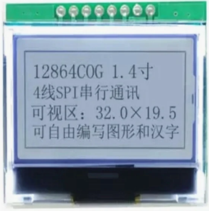
The ST7565 Mini is a versatile graphic LCD controller designed to drive monochrome LCD displays. It supports a variety of display sizes and resolutions, making it a popular choice for embedded systems requiring text and graphical output. The controller features both serial and parallel interfaces, allowing seamless integration with microcontrollers such as the Arduino UNO. Its low power consumption and flexible design make it ideal for battery-powered devices, industrial control panels, and portable electronics.
Explore Projects Built with st7565 mini

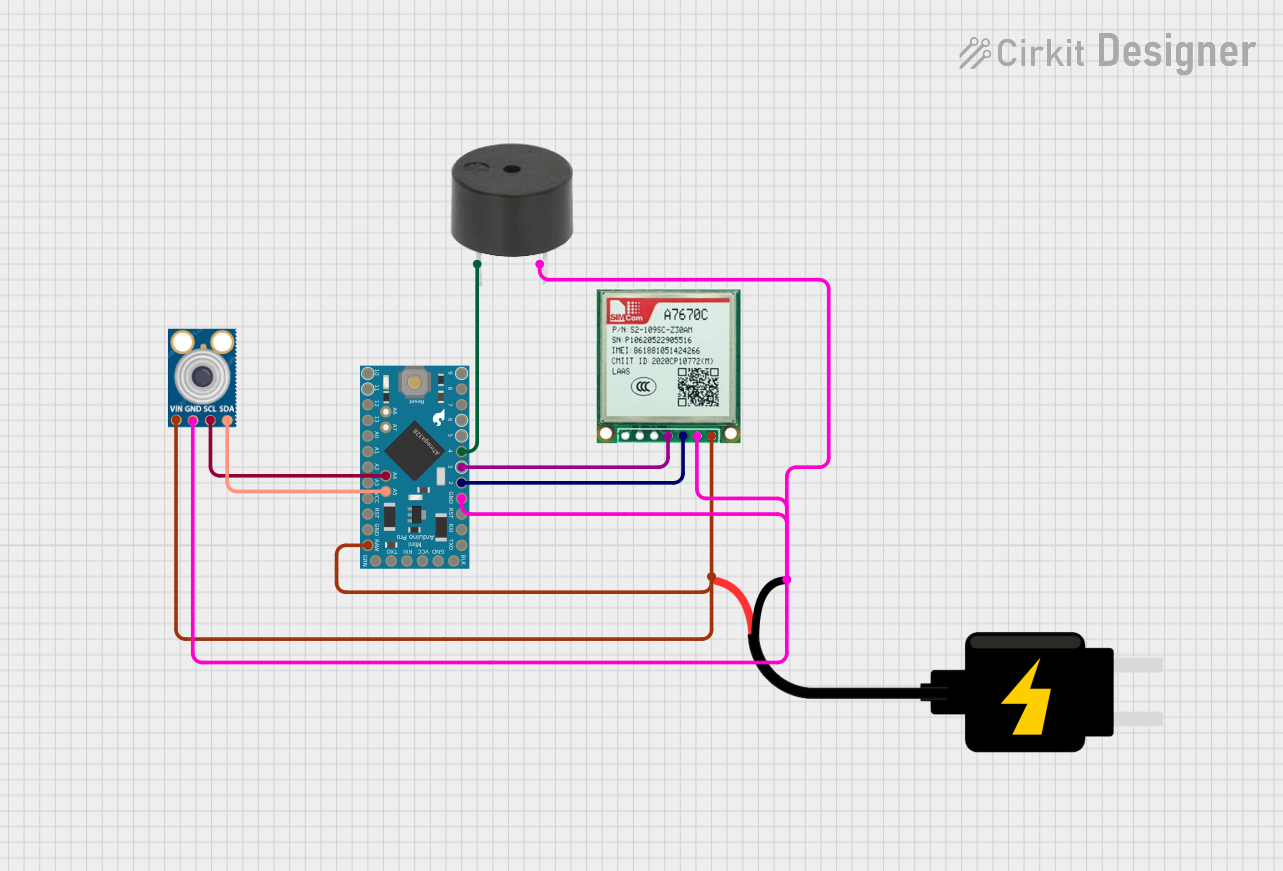


Explore Projects Built with st7565 mini
Common Applications
- Embedded systems requiring graphical or textual displays
- Industrial control panels
- Portable devices and battery-powered electronics
- Consumer electronics such as clocks, thermometers, and handheld devices
Technical Specifications
The ST7565 Mini is designed to provide efficient control of LCD displays. Below are its key technical specifications:
Key Technical Details
- Operating Voltage: 2.4V to 3.3V (logic level)
- Interface: Serial (SPI) or Parallel (8-bit/4-bit)
- Display Resolution: Supports up to 132x64 pixels
- Current Consumption: ~0.3mA (typical, during operation)
- Temperature Range: -20°C to +70°C
- Built-in Features: On-chip oscillator, contrast control, and display RAM
- Backlight Support: Compatible with LED backlights (requires external driver)
Pin Configuration and Descriptions
The ST7565 Mini typically has the following pin configuration:
| Pin Name | Pin Number | Description |
|---|---|---|
| VDD | 1 | Power supply (2.4V to 3.3V) |
| VSS | 2 | Ground connection |
| A0 | 3 | Data/Command control pin (High = Data, Low = Command) |
| CS | 4 | Chip Select (Active Low) |
| RST | 5 | Reset pin (Active Low) |
| SCL | 6 | Serial Clock input (used in SPI mode) |
| SDA | 7 | Serial Data input/output (used in SPI mode) |
| DB0-DB7 | 8-15 | Parallel data bus (used in parallel mode; DB0-DB3 optional for 4-bit mode) |
| LED+ | 16 | Backlight positive terminal (requires external current-limiting resistor) |
| LED- | 17 | Backlight negative terminal (connect to ground) |
Note: The exact pinout may vary depending on the specific module or breakout board used. Always refer to the datasheet of your specific ST7565 Mini module.
Usage Instructions
The ST7565 Mini can be used in either serial (SPI) or parallel mode, depending on the application and microcontroller compatibility. Below are the steps to integrate and use the ST7565 Mini in a circuit.
Connecting the ST7565 Mini to an Arduino UNO (SPI Mode)
Wiring:
- Connect the
VDDpin to the Arduino's3.3Vpin. - Connect the
VSSpin to the Arduino'sGND. - Connect the
A0pin to a digital pin on the Arduino (e.g.,D9). - Connect the
CSpin to a digital pin on the Arduino (e.g.,D10). - Connect the
RSTpin to a digital pin on the Arduino (e.g.,D8). - Connect the
SCLpin to the Arduino'sD13(SPI clock). - Connect the
SDApin to the Arduino'sD11(SPI MOSI). - If using a backlight, connect
LED+to5Vthrough a 220-ohm resistor andLED-toGND.
- Connect the
Install Required Libraries:
- Install the
Adafruit_ST7565library or any compatible library for the ST7565 controller.
- Install the
Example Code: Below is an example Arduino sketch to initialize the ST7565 Mini and display text:
#include <Adafruit_GFX.h>       // Graphics library for text and shapes
#include <Adafruit_ST7565.h>   // Library for ST7565 controller

// Define pin connections
#define A0_PIN 9               // Data/Command pin
#define RST_PIN 8              // Reset pin
#define CS_PIN 10              // Chip Select pin

// Create an instance of the ST7565 display
Adafruit_ST7565 display(CS_PIN, A0_PIN, RST_PIN);

void setup() {
  // Initialize the display
  display.begin(0x18);         // Contrast value (adjust as needed)
  display.clearDisplay();      // Clear the display buffer

  // Display a message
  display.setTextSize(1);      // Set text size to 1 (smallest)
  display.setTextColor(BLACK); // Set text color to black
  display.setCursor(0, 0);     // Set cursor to top-left corner
  display.print("Hello, ST7565!"); // Print text to the display
  display.display();           // Update the display with the buffer content
}

void loop() {
  // Nothing to do here
}
Important Considerations
- Power Supply: Ensure the ST7565 Mini is powered with 3.3V. Using 5V may damage the controller.
- Backlight: If using the backlight, always include a current-limiting resistor to prevent damage.
- Contrast Adjustment: The contrast value in the
begin()function may need to be adjusted based on the display and operating conditions. - SPI Mode: Ensure the microcontroller's SPI pins are correctly configured and not shared with other peripherals.
Troubleshooting and FAQs
Common Issues and Solutions
Display Not Turning On:
- Verify all connections, especially power (VDD and VSS).
- Ensure the
RSTpin is properly connected and initialized in the code.
No Text or Graphics Displayed:
- Check the
CS,A0, andSDA/SCLconnections. - Ensure the correct library is installed and initialized in the code.
- Check the
Faint or No Backlight:
- Verify the backlight connections (
LED+andLED-). - Use an appropriate resistor to limit current to the backlight.
- Verify the backlight connections (
Contrast Issues:
- Adjust the contrast value in the
begin()function. - Ensure the power supply voltage is stable and within the specified range.
- Adjust the contrast value in the
FAQs
Q: Can the ST7565 Mini be used with 5V microcontrollers?
A: Yes, but you must use level shifters or voltage dividers to step down the logic signals to 3.3V.
Q: How do I switch between SPI and parallel mode?
A: The mode is typically determined by hardware configuration (e.g., solder jumpers or pin settings). Refer to your module's datasheet for details.
Q: What is the maximum supported resolution?
A: The ST7565 Mini supports resolutions up to 132x64 pixels.
By following this documentation, you should be able to successfully integrate and use the ST7565 Mini in your projects.