How to Use Terminal Block BLUE: Examples, Pinouts, and Specs
Introduction
A Terminal Block BLUE is an electrical connector that provides a secure and organized connection point for multiple wires in a circuit. It is commonly used in electrical and electronic systems to simplify wiring, ensure reliable connections, and allow for easy maintenance or modifications. The blue color of the terminal block often signifies a specific function, such as a neutral or ground connection, depending on the wiring standards being followed.
Explore Projects Built with Terminal Block BLUE


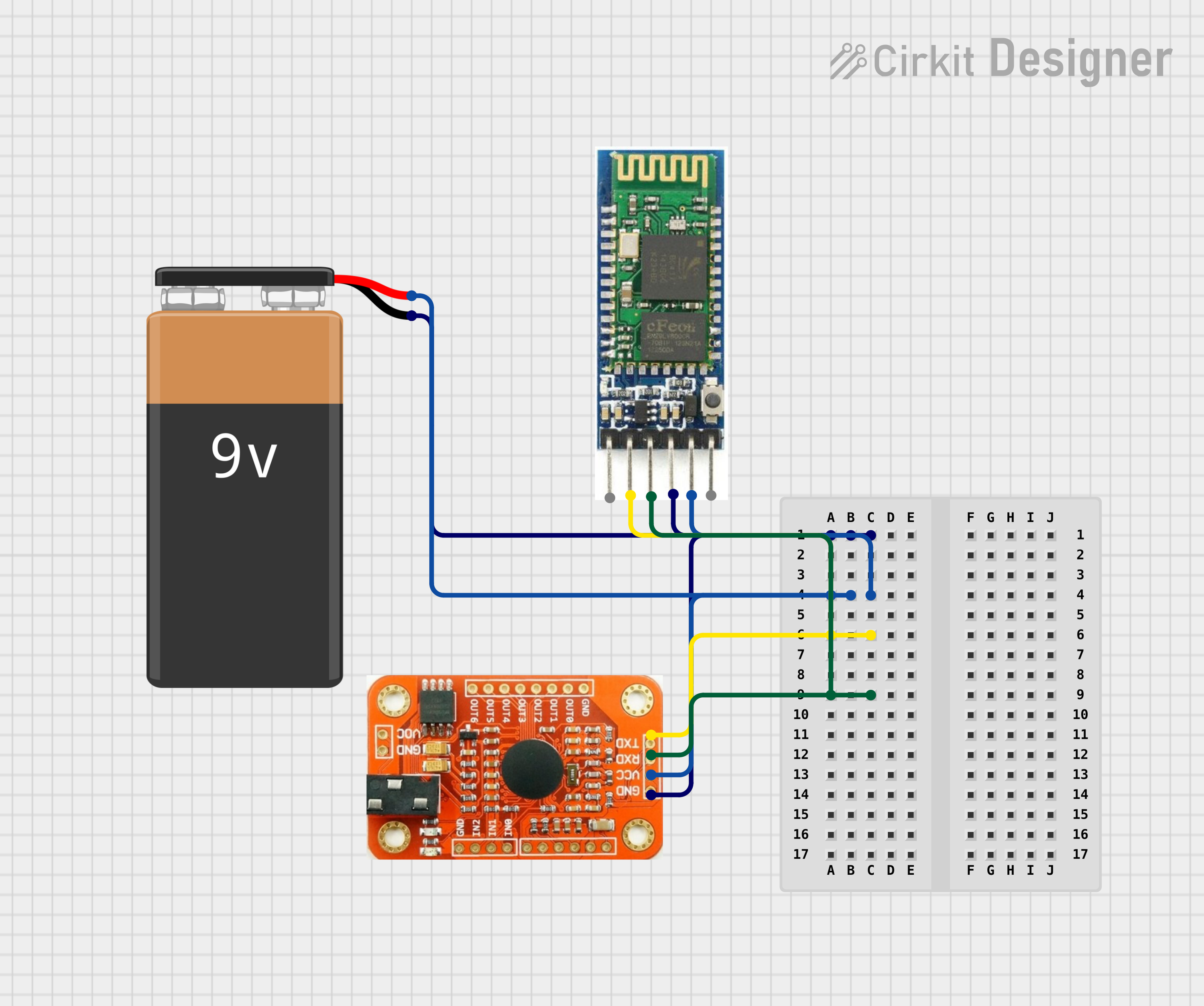
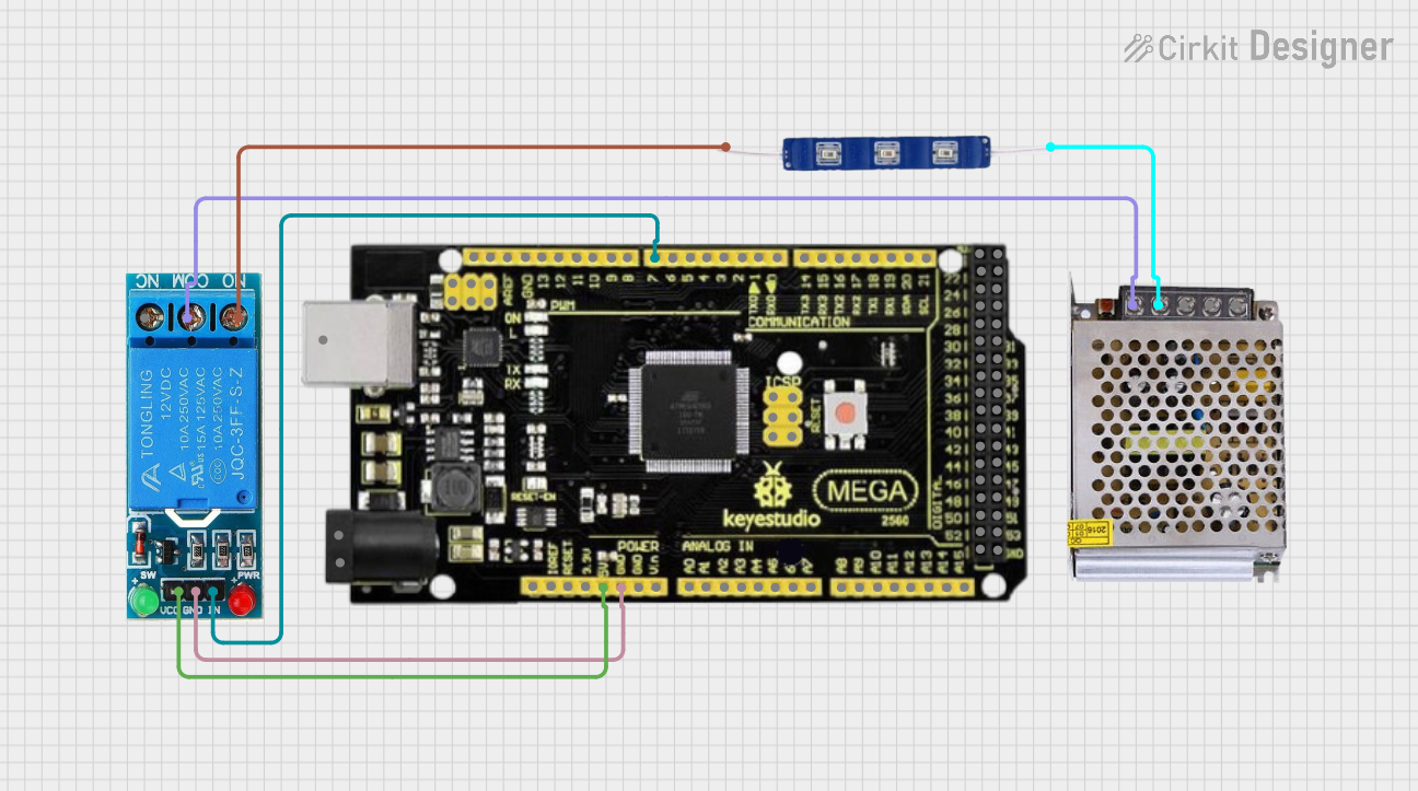
Explore Projects Built with Terminal Block BLUE
Common Applications and Use Cases
- Electrical distribution panels for organizing and connecting wires.
- Industrial control systems for managing multiple signal or power lines.
- Home automation systems for connecting sensors, actuators, and controllers.
- Prototyping and testing circuits in laboratories or workshops.
- Renewable energy systems, such as solar panel installations, for wire management.
Technical Specifications
Key Technical Details
- Material: Flame-retardant plastic housing (typically polyamide or similar material).
- Rated Voltage: Up to 600V (varies by model and manufacturer).
- Rated Current: Typically 10A to 30A, depending on the terminal block size.
- Wire Size Compatibility: 22 AWG to 10 AWG (varies by model).
- Connection Type: Screw or spring clamp terminals.
- Operating Temperature: -40°C to +105°C.
- Mounting Style: DIN rail or panel mount.
Pin Configuration and Descriptions
Terminal blocks do not have "pins" in the traditional sense but instead feature connection points for wires. Below is a table describing the key parts of a typical Terminal Block BLUE:
| Part | Description |
|---|---|
| Wire Entry Points | Openings where wires are inserted for connection. |
| Screw Terminals | Screws that secure the wires in place (for screw-type terminal blocks). |
| Spring Clamps | Spring-loaded clamps that hold wires securely (for spring-type terminal blocks). |
| Mounting Slots | Slots or clips for attaching the terminal block to a DIN rail or panel. |
| Insulation Barriers | Dividers between terminals to prevent short circuits. |
Usage Instructions
How to Use the Terminal Block BLUE in a Circuit
Prepare the Wires:
- Strip the insulation from the ends of the wires to expose approximately 5-10mm of conductor.
- Ensure the wire size matches the terminal block's specifications (e.g., 22 AWG to 10 AWG).
Insert the Wires:
- For screw-type terminal blocks:
- Loosen the screw terminal using a screwdriver.
- Insert the stripped wire into the wire entry point.
- Tighten the screw to secure the wire.
- For spring-type terminal blocks:
- Press down on the spring clamp to open the wire entry point.
- Insert the stripped wire and release the clamp to secure it.
- For screw-type terminal blocks:
Mount the Terminal Block:
- Attach the terminal block to a DIN rail or panel using the provided mounting slots or clips.
Connect the Circuit:
- Repeat the process for all wires, ensuring proper connections according to the circuit diagram.
- Verify that all connections are secure and that there are no exposed conductors.
Important Considerations and Best Practices
- Always ensure the terminal block's voltage and current ratings are suitable for your application.
- Use a torque screwdriver to avoid over-tightening screws, which can damage the terminal block or wires.
- Label the terminal block connections for easy identification and troubleshooting.
- Avoid mixing wire sizes in the same terminal to ensure a secure connection.
- If using the terminal block for neutral or ground connections, follow the appropriate wiring standards for your region.
Example: Connecting to an Arduino UNO
While terminal blocks are not directly connected to an Arduino UNO, they can be used to organize and distribute power or signals to and from the Arduino. For example, you can use a terminal block to connect multiple sensors or actuators to the Arduino's power supply.
// Example: Distributing power to multiple sensors using a terminal block
// This code demonstrates how to power sensors connected via a terminal block.

// Define the pin used for powering sensors
const int powerPin = 5; // 5V pin on the Arduino UNO

void setup() {
  // Set the power pin as an output
  pinMode(powerPin, OUTPUT);

  // Turn on the power to the terminal block
  digitalWrite(powerPin, HIGH);

  // Note: Ensure the terminal block is securely connected to the 5V and GND
  // pins of the Arduino. Use proper wire sizes to handle the current load.
}

void loop() {
  // Your main code here
}
Troubleshooting and FAQs
Common Issues and Solutions
| Issue | Solution |
|---|---|
| Loose wire connections | Ensure screws are tightened properly or spring clamps are fully engaged. |
| Overheating of terminal block | Check that the current does not exceed the terminal block's rated capacity. |
| Wires slipping out of the terminal | Verify that the wire size matches the terminal block's specifications. |
| Short circuits between terminals | Ensure insulation barriers are intact and wires are properly inserted. |
| Difficulty mounting the terminal block | Confirm compatibility with the DIN rail or panel and use appropriate tools. |
FAQs
Can I use a Terminal Block BLUE for high-current applications?
- Yes, but ensure the terminal block's current rating matches or exceeds the application's requirements.
What does the blue color signify?
- The blue color typically indicates a neutral or ground connection, but this may vary depending on regional wiring standards.
Can I connect wires of different sizes in the same terminal?
- It is not recommended, as this can lead to poor connections and potential failures.
How do I clean or maintain a terminal block?
- Disconnect all wires and use a dry cloth or compressed air to remove dust and debris. Avoid using liquids.
By following this documentation, you can effectively use the Terminal Block BLUE in your projects while ensuring safe and reliable connections.