How to Use Adafruit PWM Servo Bonnet: Examples, Pinouts, and Specs
Introduction
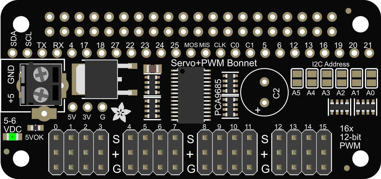
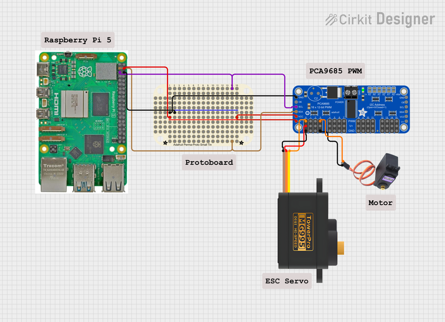
The Adafruit PWM Servo Bonnet is an add-on board designed for the Raspberry Pi that enables the control of up to 16 servo motors using the I2C interface with only two pins. Utilizing the PCA9685 PWM controller chip, it provides precise control over servo position and movement, making it an ideal choice for robotics, automation projects, and any application requiring multiple servo controls.
Explore Projects Built with Adafruit PWM Servo Bonnet
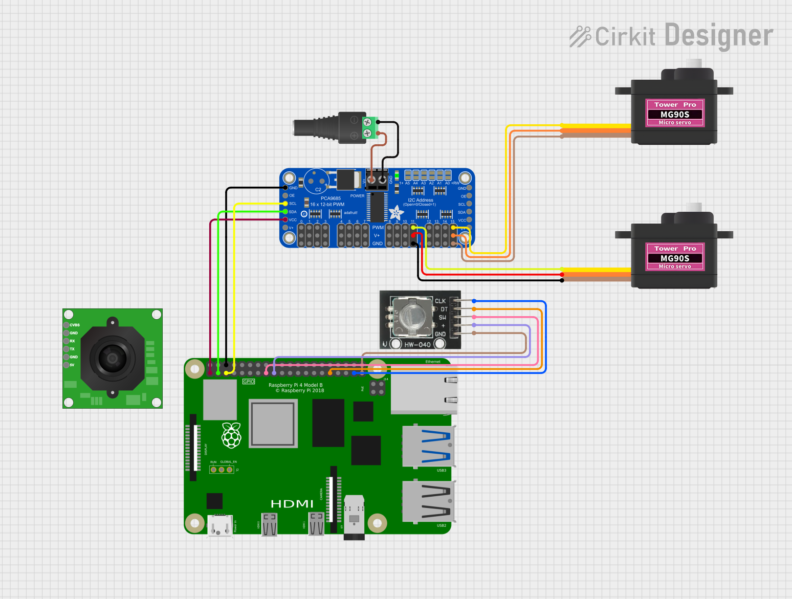
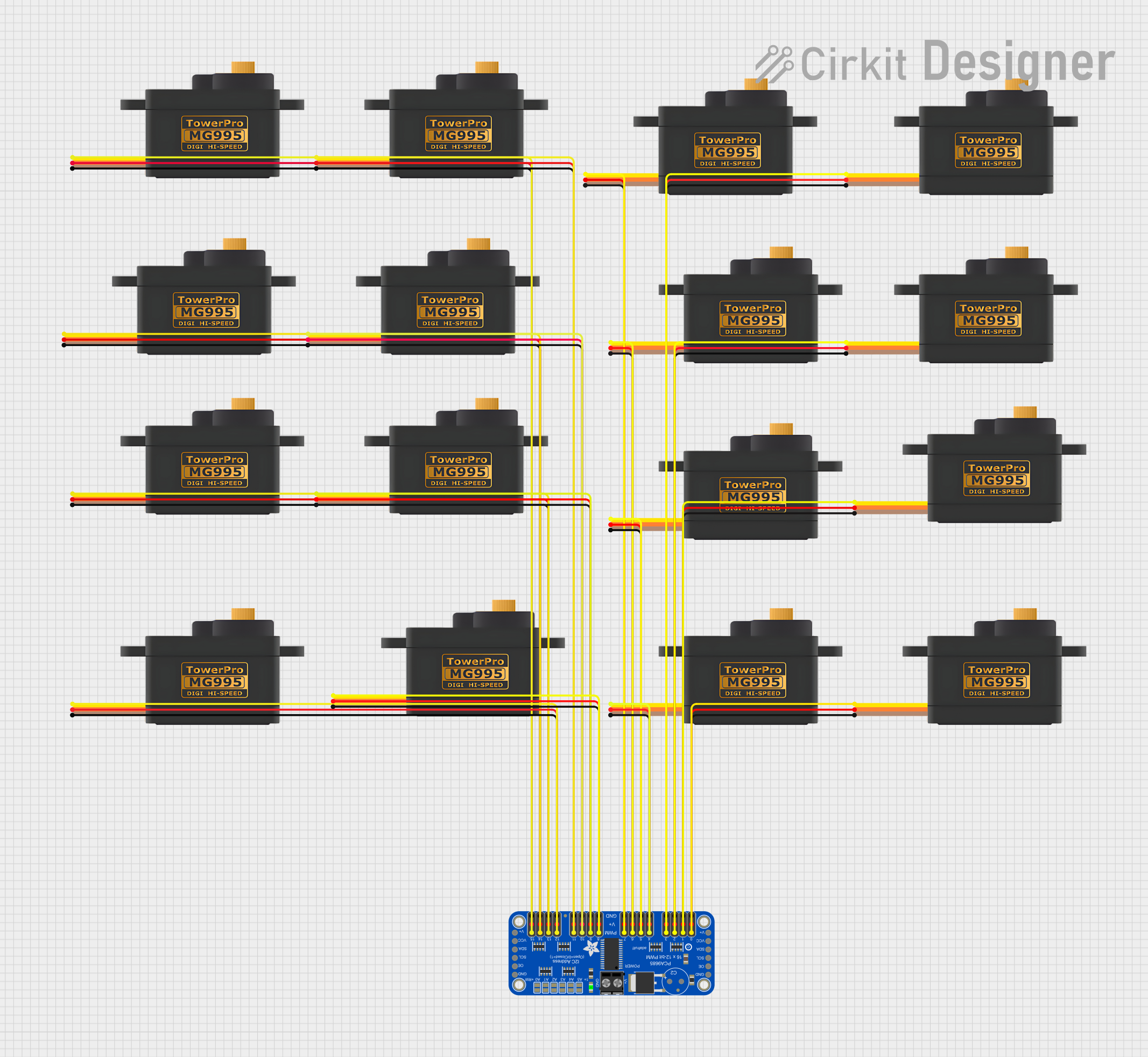
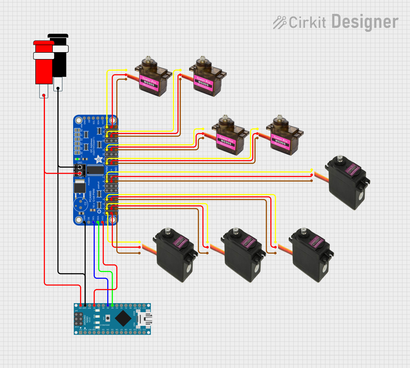
Explore Projects Built with Adafruit PWM Servo Bonnet
Common Applications and Use Cases
- Robotics arms and walkers
- Automated art installations
- Animatronics for entertainment or education
- Multi-servo projects like hexapods
- Prototyping and educational projects in schools and workshops
Technical Specifications
Key Technical Details
- Voltage: 5V (supplied via Raspberry Pi)
- Channels: 16 servo channels
- Communication Interface: I2C
- Frequency Range: 40-1000 Hz
- Resolution: 12-bit, 4096 steps
Pin Configuration and Descriptions
| Pin Number | Description |
|---|---|
| 1-16 | Servo control channels |
| V+ | Servo power supply (5V-6V) |
| SDA | I2C Data |
| SCL | I2C Clock |
| GND | Ground |
Usage Instructions
Connecting the Bonnet to Raspberry Pi
- Attach the Adafruit PWM Servo Bonnet onto the GPIO header of the Raspberry Pi.
- Ensure that the Pi is powered off before attaching the bonnet to prevent any electrical damage.
- Connect the servos to the respective channels on the bonnet, paying attention to the correct polarity of the servo wires.
Software Setup
Before using the Adafruit PWM Servo Bonnet, you need to set up the necessary software on your Raspberry Pi.
- Install the Adafruit CircuitPython library by running the following commands:
sudo pip3 install adafruit-circuitpython-servokit
- Import the library in your Python script to start using the bonnet:
from adafruit_servokit import ServoKit
kit = ServoKit(channels=16)
Controlling a Servo
To control a servo, you need to specify the channel and set the angle. Here's an example of how to set the servo on channel 0 to 90 degrees:
kit.servo[0].angle = 90
Important Considerations and Best Practices
- Always ensure that the power supply to the servos is sufficient and stable.
- Do not exceed the recommended voltage as it may damage the servos or the bonnet.
- When controlling multiple servos, be mindful of the power draw and consider using an external power source if necessary.
Troubleshooting and FAQs
Common Issues
- Servos not responding: Check the I2C connection and ensure that the servos are correctly connected with proper polarity.
- Jittery servo movement: This can be due to an inadequate power supply. Ensure that the power supply is stable and capable of delivering sufficient current.
Solutions and Tips for Troubleshooting
- Verify that the Raspberry Pi and the Adafruit PWM Servo Bonnet are powered correctly.
- Check the I2C address of the bonnet if the Pi is not detecting it. Use
i2cdetect -y 1to scan for connected I2C devices. - Ensure that the Adafruit CircuitPython library is installed and up-to-date.
FAQs
Q: Can I power the servos directly from the Raspberry Pi? A: It is not recommended to power multiple servos directly from the Raspberry Pi as it may not provide sufficient current and could potentially damage the Pi.
Q: How do I change the I2C address of the bonnet? A: The I2C address can be changed by soldering the address jumpers on the back of the bonnet. Refer to the Adafruit guide for detailed instructions.
Q: Can I use this bonnet with other single-board computers? A: While designed for the Raspberry Pi, the bonnet may work with other single-board computers that support I2C communication, but this is not guaranteed.
For further assistance, consult the Adafruit PWM Servo Bonnet forums and the extensive Adafruit learning system online.