How to Use oled circuit image: Examples, Pinouts, and Specs
Introduction
An OLED (Organic Light Emitting Diode) circuit image typically represents a schematic or layout of a circuit that utilizes OLED technology for display purposes. OLEDs are renowned for their vibrant colors, high contrast, and ability to emit light without requiring a backlight. This makes them highly efficient and ideal for use in various electronic displays, including wearables, smartphones, and embedded systems.
Common applications of OLED circuits include:
- Display modules for microcontroller-based projects (e.g., Arduino, Raspberry Pi)
- Wearable devices and smartwatches
- Portable medical devices
- Consumer electronics such as MP3 players and digital cameras
- Industrial control panels and instrumentation
Explore Projects Built with oled circuit image

Explore Projects Built with oled circuit image
Technical Specifications
Below are the general technical specifications for a typical OLED display module used in circuits:
| Parameter | Specification |
|---|---|
| Display Type | OLED (Organic Light Emitting Diode) |
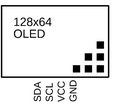
| Resolution | 128x64 pixels (common) |
| Interface | I2C or SPI |
| Operating Voltage | 3.3V to 5V |
| Operating Current | ~20mA (varies with brightness) |
| Viewing Angle | ~160° |
| Pixel Color | Monochrome (white, blue, or yellow) |
| Dimensions | Varies (e.g., 0.96-inch diagonal display) |
| Driver IC | SSD1306 (commonly used) |
Pin Configuration
The pin configuration for a typical OLED module (I2C interface) is as follows:
| Pin Name | Description |
|---|---|
| VCC | Power supply (3.3V or 5V) |
| GND | Ground |
| SCL | Serial Clock Line (I2C communication) |
| SDA | Serial Data Line (I2C communication) |
For an SPI interface OLED module, the pin configuration may include additional pins such as CS (Chip Select) and DC (Data/Command).
Usage Instructions
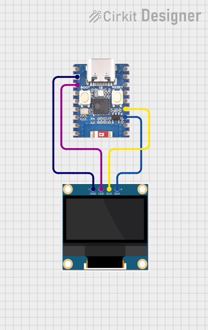
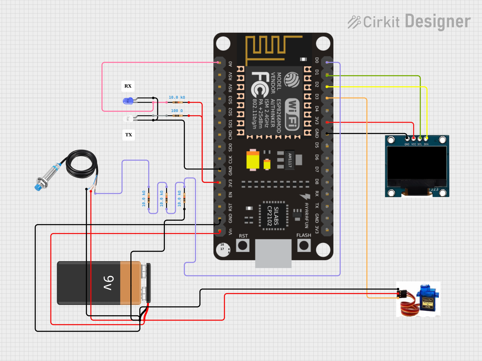
How to Use the Component in a Circuit
- Power Supply: Connect the
VCCpin to a 3.3V or 5V power source, depending on the module's specifications. Connect theGNDpin to the ground of your circuit. - Communication Interface:
- For I2C: Connect the
SCLandSDApins to the corresponding I2C pins on your microcontroller (e.g., Arduino UNO: A5 for SCL, A4 for SDA). - For SPI: Connect the
CS,DC, and other SPI pins to the appropriate microcontroller pins.
- For I2C: Connect the
- Pull-Up Resistors: If using I2C, ensure pull-up resistors (typically 4.7kΩ) are connected to the
SCLandSDAlines. - Driver Library: Install the appropriate driver library for your microcontroller. For example, the Adafruit SSD1306 library is commonly used for Arduino.
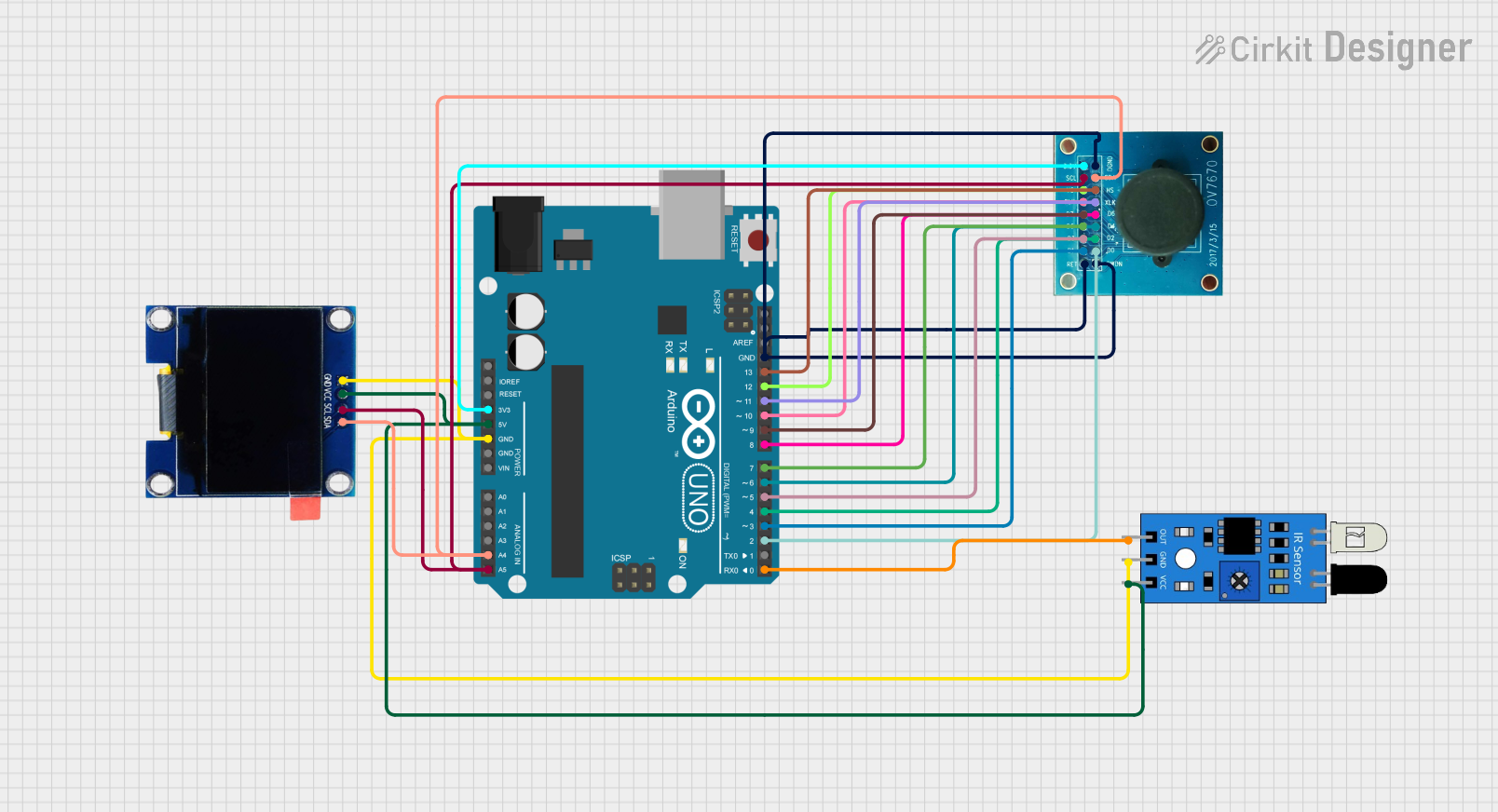
Example: Connecting an OLED to an Arduino UNO (I2C)
Below is an example of how to connect and program an OLED module with an Arduino UNO using the Adafruit SSD1306 library.
Circuit Connections
| OLED Pin | Arduino UNO Pin |
|---|---|
| VCC | 5V |
| GND | GND |
| SCL | A5 |
| SDA | A4 |
Arduino Code
#include <Wire.h>
#include <Adafruit_GFX.h>
#include <Adafruit_SSD1306.h>

// Define OLED display width and height
#define SCREEN_WIDTH 128
#define SCREEN_HEIGHT 64

// Create an SSD1306 display object
Adafruit_SSD1306 display(SCREEN_WIDTH, SCREEN_HEIGHT, &Wire, -1);

void setup() {
  // Initialize serial communication for debugging
  Serial.begin(9600);

  // Initialize the OLED display
  if (!display.begin(SSD1306_I2C_ADDRESS, 0x3C)) {
    // If initialization fails, print an error message
    Serial.println(F("SSD1306 allocation failed"));
    for (;;); // Halt the program
  }

  // Clear the display buffer
  display.clearDisplay();

  // Display a welcome message
  display.setTextSize(1); // Set text size
  display.setTextColor(SSD1306_WHITE); // Set text color
  display.setCursor(0, 0); // Set cursor position
  display.println(F("Hello, OLED!")); // Print text
  display.display(); // Update the display
}

void loop() {
  // Add your code here to update the display dynamically
}
Important Considerations and Best Practices
- Voltage Compatibility: Ensure the OLED module's operating voltage matches your microcontroller's logic level (3.3V or 5V).
- Brightness Control: Prolong the OLED's lifespan by reducing brightness when full intensity is not required.
- Library Compatibility: Use a library compatible with your OLED's driver IC (e.g., SSD1306 or SH1106).
- Avoid Burn-In: Prevent static images from being displayed for extended periods to avoid burn-in effects.
Troubleshooting and FAQs
Common Issues and Solutions
OLED Display Not Turning On
- Cause: Incorrect wiring or insufficient power supply.
- Solution: Double-check all connections and ensure the power supply meets the module's requirements.
No Text or Graphics Displayed
- Cause: Incorrect I2C address or uninitialized display.
- Solution: Verify the I2C address (default is 0x3C) and ensure the display is initialized in the code.
Flickering or Unstable Display
- Cause: Noise on the I2C or SPI lines.
- Solution: Use shorter wires and add decoupling capacitors near the OLED module.
Burn-In or Image Retention
- Cause: Static images displayed for long durations.
- Solution: Implement a screen saver or periodically refresh the display content.
FAQs
Q: Can I use the OLED module with a 3.3V microcontroller?
A: Yes, most OLED modules are compatible with both 3.3V and 5V logic levels. Check the module's datasheet to confirm.
Q: How do I change the I2C address of the OLED module?
A: Some modules allow changing the I2C address by soldering jumpers on the back of the PCB. Refer to the module's documentation for details.
Q: Can I use multiple OLED displays in the same circuit?
A: Yes, you can use multiple displays by assigning unique I2C addresses or using separate SPI chip select lines.
Q: What is the typical lifespan of an OLED display?
A: The lifespan varies depending on usage and brightness settings but is typically around 10,000 to 50,000 hours.