
How to Use Textile Potentiometer: Examples, Pinouts, and Specs

 Design with Textile Potentiometer in Cirkit Designer
Introduction
The Textile Potentiometer (PW064), manufactured by Plug and Wear, is a variable resistor made from conductive fabric. This innovative component allows for adjustable resistance in electronic circuits by physically interacting with the textile material. Its soft and flexible nature makes it ideal for integration into wearable technology and soft electronics.
Explore Projects Built with Textile Potentiometer
 Open Project in Cirkit Designer
 Open Project in Cirkit Designer
 Open Project in Cirkit Designer
 Open Project in Cirkit Designer
Explore Projects Built with Textile Potentiometer
Open Project in Cirkit DesignerOpen Project in Cirkit DesignerOpen Project in Cirkit DesignerOpen Project in Cirkit DesignerCommon Applications and Use Cases
- Wearable devices for user input (e.g., volume control, gesture sensing)
- Soft robotics and e-textiles
- Pressure-sensitive controls
- Interactive art installations
- Prototyping for flexible and stretchable electronics
Technical Specifications
The following table outlines the key technical details of the PW064 Textile Potentiometer:
| Parameter | Value |
|---|---|
| Manufacturer | Plug and Wear |
| Part ID | PW064 |
| Resistance Range | 0 Ω to 10 kΩ |
| Operating Voltage | 0 V to 5 V |
| Power Rating | 0.1 W |
| Material | Conductive fabric |
| Dimensions | Customizable (varies by design) |
| Operating Temperature | -10°C to 60°C |
| Lifespan | > 100,000 cycles |
Pin Configuration and Descriptions
The Textile Potentiometer typically has three connection points (pins), which are described below:
| Pin | Name | Description |
|---|---|---|
| 1 | VCC | Connects to the positive voltage supply (e.g., 5V from a microcontroller). |
| 2 | Wiper (Signal) | Outputs the variable resistance value based on the position of the wiper. |
| 3 | GND | Connects to the ground of the circuit. |
Usage Instructions
How to Use the Textile Potentiometer in a Circuit
Connect the Pins:
- Attach Pin 1 (VCC) to the positive voltage supply (e.g., 5V).
- Connect Pin 3 (GND) to the ground of your circuit.
- Use Pin 2 (Wiper) to read the variable resistance output.
Integrate with a Microcontroller:
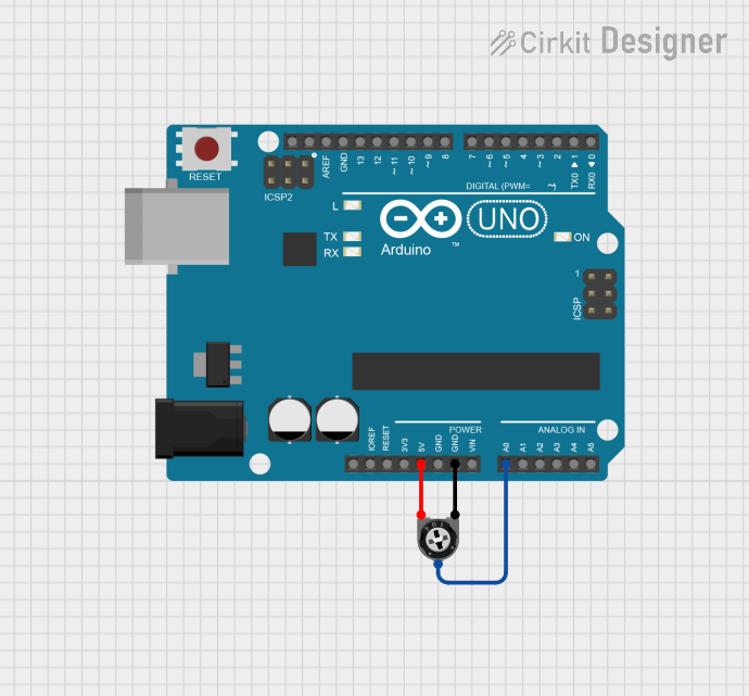
- The wiper pin can be connected to an analog input pin of a microcontroller (e.g., Arduino UNO) to measure the resistance value as a voltage.
Calibrate the Output:
- Map the analog readings to the desired range (e.g., 0 to 10 kΩ or 0 to 100%).
Important Considerations and Best Practices
- Avoid excessive stretching or folding of the textile potentiometer to maintain its lifespan.
- Ensure proper electrical connections to avoid noise or inaccurate readings.
- Use pull-down resistors if necessary to stabilize the signal.
- Keep the textile clean and free from debris to ensure consistent performance.
Example Code for Arduino UNO
The following example demonstrates how to read the resistance value of the textile potentiometer using an Arduino UNO:
// Define the analog pin connected to the wiper (signal) of the potentiometer
const int potPin = A0;

void setup() {
  // Initialize serial communication for debugging
  Serial.begin(9600);
}

void loop() {
  // Read the analog value from the potentiometer
  int potValue = analogRead(potPin);

  // Map the analog value (0-1023) to the resistance range (0-10 kΩ)
  float resistance = map(potValue, 0, 1023, 0, 10000);

  // Print the resistance value to the Serial Monitor
  Serial.print("Resistance: ");
  Serial.print(resistance);
  Serial.println(" ohms");

  // Add a short delay for stability
  delay(500);
}
Troubleshooting and FAQs
Common Issues and Solutions
Inconsistent Readings:
- Cause: Loose connections or dirty textile surface.
- Solution: Ensure all connections are secure and clean the textile with a soft, dry cloth.
No Output Signal:
- Cause: Incorrect wiring or damaged component.
- Solution: Double-check the pin connections and test the potentiometer with a multimeter.
Signal Noise or Fluctuations:
- Cause: Electrical interference or improper grounding.
- Solution: Use shielded cables and ensure a solid ground connection.
FAQs
Q: Can the textile potentiometer be washed?
A: No, the textile potentiometer is not washable. Avoid exposing it to water or excessive moisture.
Q: What is the lifespan of the PW064 Textile Potentiometer?
A: The component is rated for over 100,000 cycles under normal operating conditions.
Q: Can this component be used with flexible PCBs?
A: Yes, the textile potentiometer is compatible with flexible PCBs and other soft electronic systems.
Q: How do I measure the resistance directly?
A: Use a multimeter to measure the resistance between the wiper pin and either the VCC or GND pin.
By following this documentation, users can effectively integrate the PW064 Textile Potentiometer into their projects and troubleshoot common issues with ease.