How to Use Mtiny ESP8266 ESP-12S: Examples, Pinouts, and Specs
Introduction
The Mtiny ESP8266 ESP-12S is a highly integrated Wi-Fi module developed by Makerlabvn, designed for a wide range of Internet of Things (IoT) applications. This module is based on the popular ESP8266 microcontroller and offers a complete and self-contained Wi-Fi networking solution. It can host applications or offload Wi-Fi networking functions from another microcontroller. Common applications include smart home devices, wireless sensors, and various other IoT devices.
Explore Projects Built with Mtiny ESP8266 ESP-12S

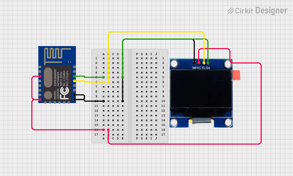

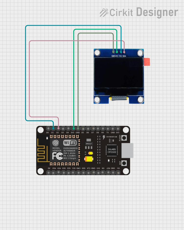
Explore Projects Built with Mtiny ESP8266 ESP-12S
Technical Specifications
General Features
- Integrated Tensilica L106 ultra-low-power 32-bit microcontroller
- Wi-Fi Direct (P2P), soft-AP
- Integrated TCP/IP protocol stack
- Integrated TR switch, balun, LNA, power amplifier, and matching network
- Integrated PLLs, regulators, DCXO, and power management units
- Supports antenna diversity
- Power down leakage current of < 10uA
- Integrated low-power 32-bit CPU could be used as an application processor
- SDIO 1.1/2.0, SPI, UART
- STBC, 1x1 MIMO, 2x1 MIMO
- A-MPDU & A-MSDU aggregation & 0.4ms guard interval
- Wake up and transmit packets in < 2ms
- Standby power consumption of < 1.0mW (DTIM3)
Electrical Characteristics
- Power Supply: 3.0V to 3.6V
- Current Consumption: 80mA (typical operation)
- Operating Temperature Range: -40°C to 125°C
Pin Configuration and Descriptions
| Pin Number | Name | Description |
|---|---|---|
| 1 | GND | Ground |
| 2 | GPIO2 | General Purpose Input/Output 2 |
| 3 | GPIO0 | General Purpose Input/Output 0 |
| 4 | RX | UART Receive Pin |
| 5 | TX | UART Transmit Pin |
| 6 | CH_PD | Chip Power-Down Pin. High = ON, Low = OFF |
| 7 | GPIO15 | General Purpose Input/Output 15 |
| 8 | GPIO13 | General Purpose Input/Output 13 |
| 9 | VCC | Power Supply (3.0V to 3.6V) |
| 10 | GPIO12 | General Purpose Input/Output 12 |
| 11 | GPIO14 | General Purpose Input/Output 14 |
| 12 | GPIO16 | General Purpose Input/Output 16 |
| 13 | ADC | Analog to Digital Converter Input |
| 14 | RESET | Reset Pin. Active low. |
| 15 | GPIO5 | General Purpose Input/Output 5 |
| 16 | GPIO4 | General Purpose Input/Output 4 |
Usage Instructions
Basic Setup
To use the Mtiny ESP8266 ESP-12S module in a circuit:
- Connect the VCC pin to a 3.3V power supply.
- Connect the GND pin to the ground of the power supply.
- Ensure that CH_PD is connected to VCC to power on the chip.
- Connect UART pins (RX, TX) to a USB-to-Serial converter for programming and debugging.
- Use GPIO pins for interfacing with sensors, actuators, or other peripherals as needed.
Programming
The ESP-12S can be programmed using the Arduino IDE:
- Install the ESP8266 board package in the Arduino IDE.
- Select the correct board and port in the Arduino IDE.
- Write or load your program.
- Ensure GPIO0 is grounded to enable the flash mode.
- Press the RESET button or cycle power to reset the module.
- Upload the program.
Example Blink Code for Arduino IDE
// Define the LED pin
const int LED_PIN = 2; // Use GPIO2 for the built-in LED

void setup() {
  // Initialize the LED pin as an output
  pinMode(LED_PIN, OUTPUT);
}

void loop() {
  // Turn the LED on
  digitalWrite(LED_PIN, HIGH);
  delay(1000); // Wait for a second
  // Turn the LED off
  digitalWrite(LED_PIN, LOW);
  delay(1000); // Wait for a second
}
Best Practices
- Always use a 3.3V power supply to avoid damaging the module.
- Use a logic level converter when interfacing with 5V logic devices.
- Avoid exposing the module to temperatures outside the specified range.
- Ensure proper decoupling with a 0.1uF capacitor close to the VCC pin.
Troubleshooting and FAQs
Common Issues
- Module not responding: Ensure that the power supply is 3.3V and that CH_PD is connected to VCC.
- Cannot upload code: Check that GPIO0 is grounded to enable flash mode and that the correct board and port are selected in the Arduino IDE.
- Wi-Fi not connecting: Verify the Wi-Fi credentials and signal strength. Ensure the antenna is properly connected if using an external one.
FAQs
Q: Can the ESP-12S be used with a 5V power supply? A: No, the ESP-12S must be powered with a 3.0V to 3.6V supply.
Q: How do I reset the module? A: The module can be reset by pulling the RESET pin low.
Q: Can I use the ESP-12S with a battery? A: Yes, as long as the battery voltage is within the 3.0V to 3.6V range.
Q: How many GPIO pins are available on the ESP-12S? A: The ESP-12S provides access to multiple GPIO pins, as listed in the pin configuration table.
Q: What is the maximum current draw of the ESP-12S? A: The typical current consumption is 80mA during operation, but it can be higher during Wi-Fi transmission bursts.
For further assistance, consult the Makerlabvn support forums or contact technical support.