How to Use Arduino Motor Driver Expansion Board: Examples, Pinouts, and Specs
Introduction
The Arduino Motor Driver Expansion Board is a versatile circuit board designed to enable an Arduino microcontroller to control various types of motors, including DC motors, stepper motors, and servo motors. It provides the necessary power amplification and control signals to drive motors efficiently, making it an essential component for robotics, automation, and motorized projects.
Explore Projects Built with Arduino Motor Driver Expansion Board
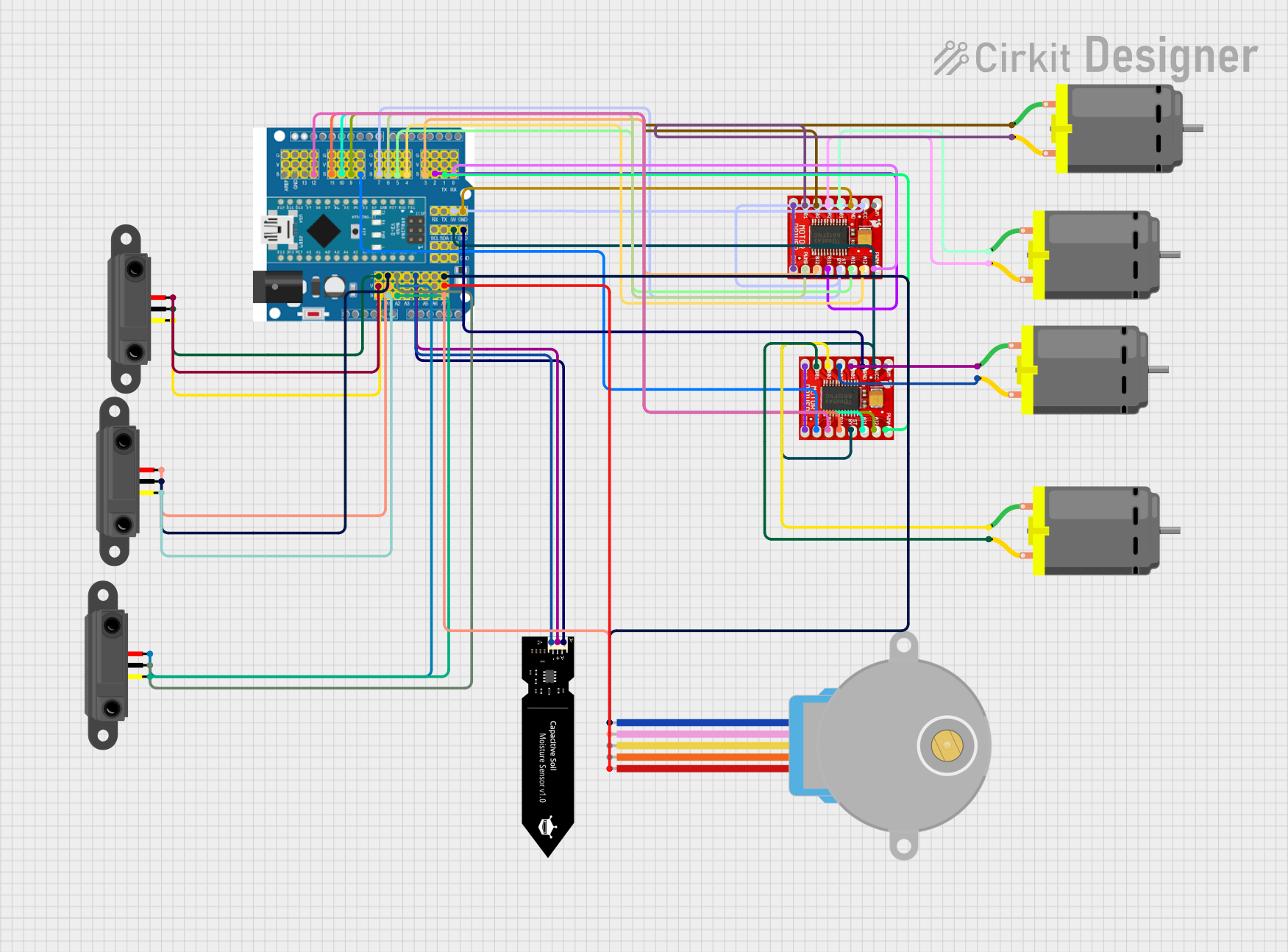
Explore Projects Built with Arduino Motor Driver Expansion Board
Common Applications and Use Cases
- Robotics: Driving wheels, arms, or other motorized components.
- Automation: Controlling conveyor belts, actuators, or other moving parts.
- DIY Projects: Building motorized toys, remote-controlled vehicles, or home automation systems.
- Prototyping: Testing motor control algorithms and designs.
Technical Specifications
Key Technical Details
- Input Voltage: 6V to 12V (depending on motor requirements)
- Output Current: Up to 2A per channel
- Motor Channels: 2 (can control two DC motors or one stepper motor)
- Control Interface: PWM (Pulse Width Modulation) and direction control pins
- Compatible Motors: DC motors, stepper motors, and servo motors
- Logic Voltage: 5V (compatible with Arduino logic levels)
- Built-in Protection: Overcurrent and thermal protection
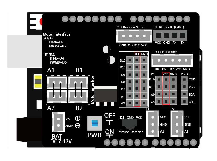
Pin Configuration and Descriptions
The Arduino Motor Driver Expansion Board typically has the following pin layout:
Motor Control Pins
| Pin Name | Description |
|---|---|
| IN1 | Control signal for Motor 1 (direction) |
| IN2 | Control signal for Motor 1 (direction) |
| IN3 | Control signal for Motor 2 (direction) |
| IN4 | Control signal for Motor 2 (direction) |
| ENA | PWM input for Motor 1 (speed control) |
| ENB | PWM input for Motor 2 (speed control) |
Power and Logic Pins
| Pin Name | Description |
|---|---|
| VCC | Logic voltage input (5V from Arduino) |
| GND | Ground connection |
| VM | Motor power supply (6V to 12V) |
Servo Motor Pins (if applicable)
| Pin Name | Description |
|---|---|
| SERVO1 | Signal pin for Servo Motor 1 |
| SERVO2 | Signal pin for Servo Motor 2 |
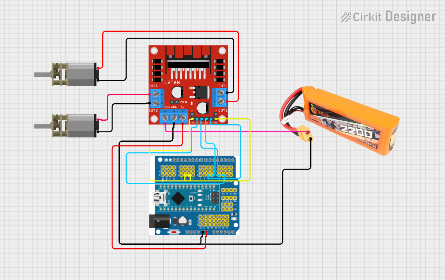
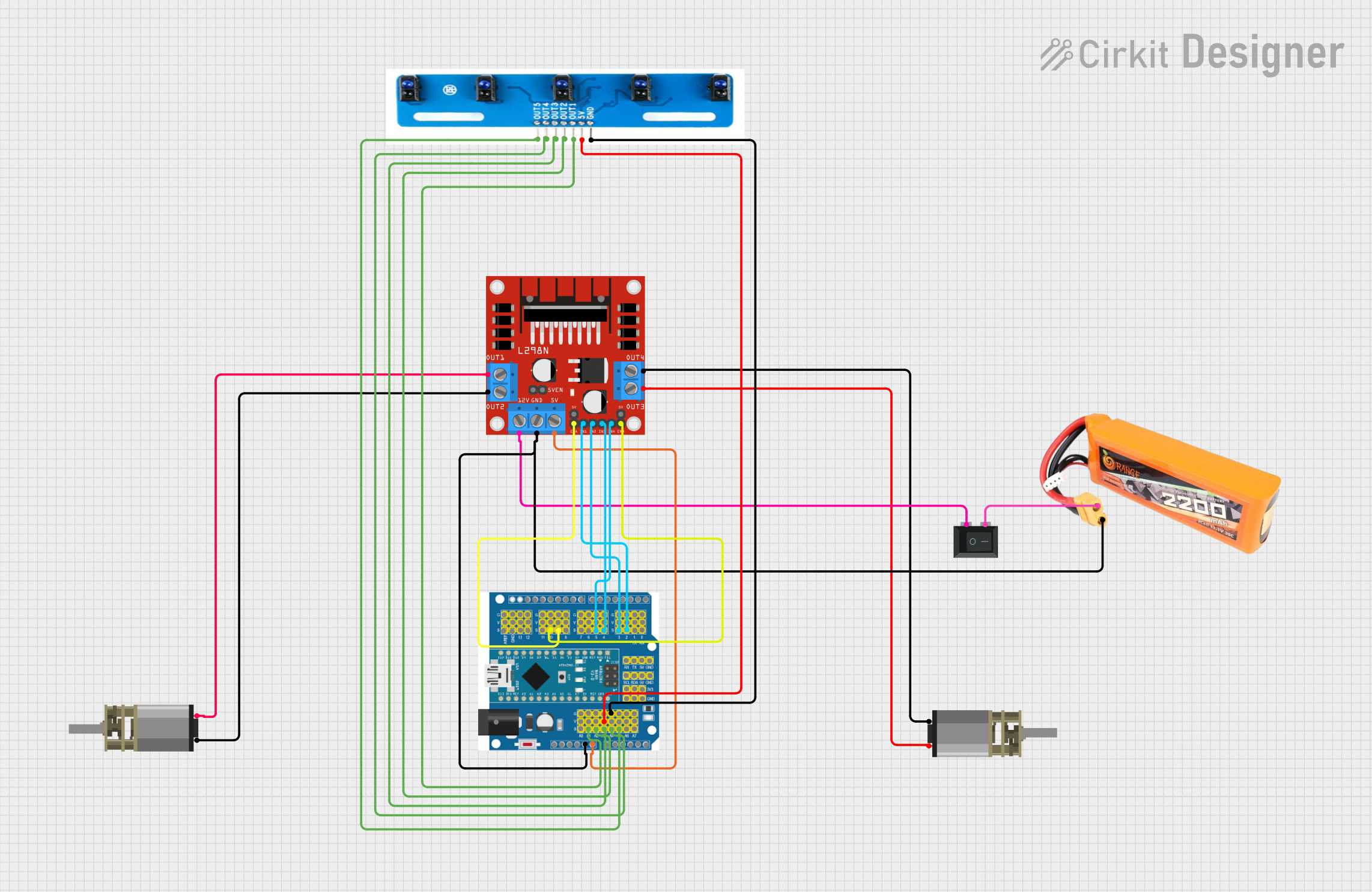
Usage Instructions
How to Use the Component in a Circuit
- Connect Power Supply:
- Connect the motor power supply (6V to 12V) to the
VMpin. - Connect the Arduino's 5V output to the
VCCpin and ground to theGNDpin.
- Connect the motor power supply (6V to 12V) to the
- Connect Motors:
- For DC motors, connect the motor terminals to the output terminals of the board (e.g., Motor 1 to OUT1 and OUT2, Motor 2 to OUT3 and OUT4).
- For stepper motors, connect the four motor wires to the appropriate output terminals.
- For servo motors, connect the signal wire to the
SERVOpin and power wires toVCCandGND.
- Connect Control Pins:
- Connect the control pins (
IN1,IN2,ENA, etc.) to the corresponding Arduino digital pins.
- Connect the control pins (
- Upload Code:
- Write and upload a motor control program to the Arduino.
Important Considerations and Best Practices
- Ensure the motor power supply voltage matches the motor's specifications.
- Avoid exceeding the current rating of the board (2A per channel).
- Use proper heat dissipation if driving high-current motors for extended periods.
- Double-check all connections to prevent short circuits or damage to the board.
- Use external power for motors if they require more current than the Arduino can supply.
Example Code for Arduino UNO
Below is an example code snippet to control a DC motor using the Arduino Motor Driver Expansion Board:
// Define motor control pins
const int ENA = 9;  // PWM pin for Motor 1 speed control
const int IN1 = 7;  // Direction pin for Motor 1
const int IN2 = 8;  // Direction pin for Motor 1

void setup() {
  // Set motor control pins as outputs
  pinMode(ENA, OUTPUT);
  pinMode(IN1, OUTPUT);
  pinMode(IN2, OUTPUT);
}

void loop() {
  // Rotate motor forward
  digitalWrite(IN1, HIGH);  // Set IN1 high
  digitalWrite(IN2, LOW);   // Set IN2 low
  analogWrite(ENA, 150);    // Set speed (0-255)

  delay(2000);  // Run motor for 2 seconds

  // Rotate motor backward
  digitalWrite(IN1, LOW);   // Set IN1 low
  digitalWrite(IN2, HIGH);  // Set IN2 high
  analogWrite(ENA, 150);    // Set speed (0-255)

  delay(2000);  // Run motor for 2 seconds

  // Stop motor
  digitalWrite(IN1, LOW);   // Set IN1 low
  digitalWrite(IN2, LOW);   // Set IN2 low
  analogWrite(ENA, 0);      // Set speed to 0

  delay(2000);  // Wait for 2 seconds
}
Troubleshooting and FAQs
Common Issues and Solutions
Motors Not Running:
- Check the power supply voltage and ensure it matches the motor's requirements.
- Verify all connections, especially the control and power pins.
- Ensure the Arduino is properly powered and the code is uploaded correctly.
Motor Running in the Wrong Direction:
- Swap the connections of
IN1andIN2(orIN3andIN4) to reverse the motor direction. - Verify the logic in your Arduino code.
- Swap the connections of
Overheating of the Board:
- Ensure the motor's current does not exceed the board's 2A per channel limit.
- Use a heat sink or fan for better heat dissipation.
Servo Motor Not Responding:
- Check the servo's power and signal connections.
- Ensure the servo signal pin is connected to a PWM-capable Arduino pin.
FAQs
Can I control more than two DC motors?
- No, this board supports up to two DC motors or one stepper motor. For more motors, consider using additional motor driver boards.
Can I use this board with a Raspberry Pi?
- Yes, but you will need to ensure the logic voltage levels are compatible (use a level shifter if necessary).
What happens if I exceed the current limit?
- The board's built-in protection will shut down the motor driver to prevent damage. Reduce the load or use a higher-rated driver.
By following this documentation, you can effectively use the Arduino Motor Driver Expansion Board in your projects!