How to Use nextion 5 inch: Examples, Pinouts, and Specs
Introduction
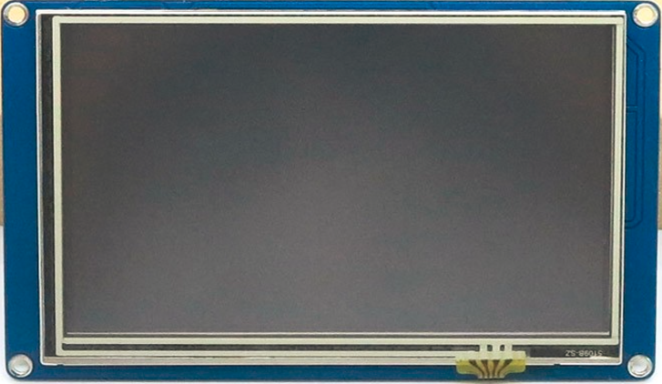
The Nextion 5-inch HMI (Human-Machine Interface) display is a versatile and user-friendly touchscreen module designed for seamless interaction with embedded systems. It features a built-in microcontroller for processing, eliminating the need for an external graphics controller. The display supports serial communication, making it easy to integrate with microcontrollers such as Arduino, Raspberry Pi, and other embedded platforms.
Explore Projects Built with nextion 5 inch
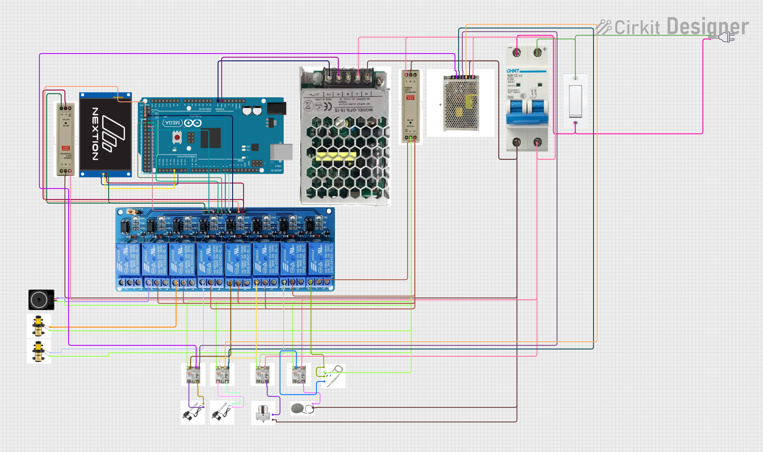


Explore Projects Built with nextion 5 inch
Common Applications and Use Cases
- Home automation systems
- Industrial control panels
- Medical devices
- IoT dashboards
- Smart appliances
- Educational and prototyping projects
Technical Specifications
The following table outlines the key technical details of the Nextion 5-inch HMI display:
| Specification | Details |
|---|---|
| Display Size | 5 inches |
| Resolution | 800 x 480 pixels |
| Touchscreen Type | Resistive |
| Communication Interface | UART (Serial) |
| Operating Voltage | 5V DC |
| Power Consumption | 500mW (typical) |
| Flash Memory | 16MB |
| RAM | 3584 bytes |
| Processor | 48 MHz Cortex-M0 |
| Operating Temperature | -20°C to 70°C |
| Dimensions | 133.5mm x 85.4mm x 5.55mm |
Pin Configuration and Descriptions
The Nextion 5-inch HMI display has a 4-pin interface for communication and power. The pin configuration is as follows:
| Pin | Name | Description |
|---|---|---|
| 1 | VCC | Power supply input (5V DC) |
| 2 | GND | Ground |
| 3 | TX | Transmit data (UART communication) |
| 4 | RX | Receive data (UART communication) |
Usage Instructions
How to Use the Component in a Circuit
- Powering the Display: Connect the
VCCpin to a 5V power source and theGNDpin to ground. - Serial Communication: Connect the
TXpin of the display to theRXpin of your microcontroller, and theRXpin of the display to theTXpin of your microcontroller. - Programming the Display:
- Use the Nextion Editor software to design the user interface (UI) and upload it to the display via a microSD card or serial connection.
- The Nextion Editor allows you to add buttons, sliders, text fields, and other UI elements.
- Microcontroller Integration:
- Use UART communication to send and receive commands between the display and your microcontroller.
- Libraries such as the Nextion Arduino library can simplify communication.
Important Considerations and Best Practices
- Ensure the power supply is stable and within the specified voltage range (5V DC).
- Use level shifters if your microcontroller operates at 3.3V logic levels to avoid damaging the display.
- Avoid touching the resistive touchscreen with sharp objects to prevent damage.
- Keep the display firmware updated for optimal performance and compatibility.
- Use the Nextion Editor's debugging tools to test your UI before deploying it to the display.
Example Code for Arduino UNO
Below is an example of how to interface the Nextion 5-inch HMI display with an Arduino UNO:
#include <Nextion.h>

// Define the serial communication for the Nextion display
// Connect the display's TX pin to Arduino pin 2 (RX)
// Connect the display's RX pin to Arduino pin 3 (TX)
SoftwareSerial nextionSerial(2, 3);

// Create a Nextion object
NexText t0 = NexText(0, 1, "t0"); // Text component on the Nextion display

void setup() {
  nextionSerial.begin(9600); // Initialize serial communication at 9600 baud
  Serial.begin(9600);        // For debugging purposes
  nexInit();                 // Initialize the Nextion display

  // Set initial text on the display
  t0.setText("Hello, Nextion!");
}

void loop() {
  // Example: Update the text on the display every 5 seconds
  static unsigned long lastUpdate = 0;
  if (millis() - lastUpdate > 5000) {
    t0.setText("Updated Text!");
    lastUpdate = millis();
  }
}
Notes:
- Install the Nextion Arduino library from the Arduino IDE Library Manager before using the code.
- Ensure the
t0component exists in your Nextion Editor project with the correct page and ID.
Troubleshooting and FAQs
Common Issues and Solutions
Display Not Powering On:
- Verify that the
VCCandGNDpins are correctly connected to a 5V power source. - Check for loose connections or damaged wires.
- Verify that the
No Communication Between Display and Microcontroller:
- Ensure the
TXandRXpins are correctly connected (crossed: TX to RX and RX to TX). - Confirm that the baud rate in your code matches the display's baud rate.
- Use a logic level shifter if your microcontroller operates at 3.3V logic levels.
- Ensure the
Touchscreen Not Responding:
- Check if the touchscreen is physically damaged.
- Ensure the UI elements in the Nextion Editor are properly configured to respond to touch events.
UI Not Displaying Correctly:
- Verify that the correct
.tftfile is uploaded to the display. - Use the Nextion Editor's debug mode to test the UI before uploading.
- Verify that the correct
FAQs
Q: Can I use the Nextion display with a Raspberry Pi?
A: Yes, the Nextion display can be used with a Raspberry Pi via UART communication. Use the GPIO pins for serial communication or a USB-to-TTL adapter.
Q: How do I update the firmware on the Nextion display?
A: Download the firmware file from the Nextion website, copy it to a microSD card, and insert the card into the display. The update process will start automatically.
Q: What is the maximum cable length for UART communication?
A: The maximum cable length depends on the baud rate and environmental factors. For reliable communication, keep the cable length under 1 meter for high baud rates.
Q: Can I use multiple Nextion displays with a single microcontroller?
A: Yes, but each display will require a separate UART interface or a software-based serial communication implementation.
Q: Is the Nextion display compatible with 3.3V microcontrollers?
A: Yes, but you must use a level shifter to convert the 3.3V logic levels to 5V for proper operation.