How to Use xt90e: Examples, Pinouts, and Specs
Introduction
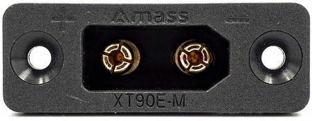
The XT90E is a high-current connector designed for use in RC (radio-controlled) applications, such as drones, electric vehicles, and other high-power systems. It features a secure locking mechanism and a compact design, ensuring reliable connections and efficient power transfer. The XT90E is known for its durability, low resistance, and ability to handle high currents, making it a popular choice for demanding applications.
Explore Projects Built with xt90e


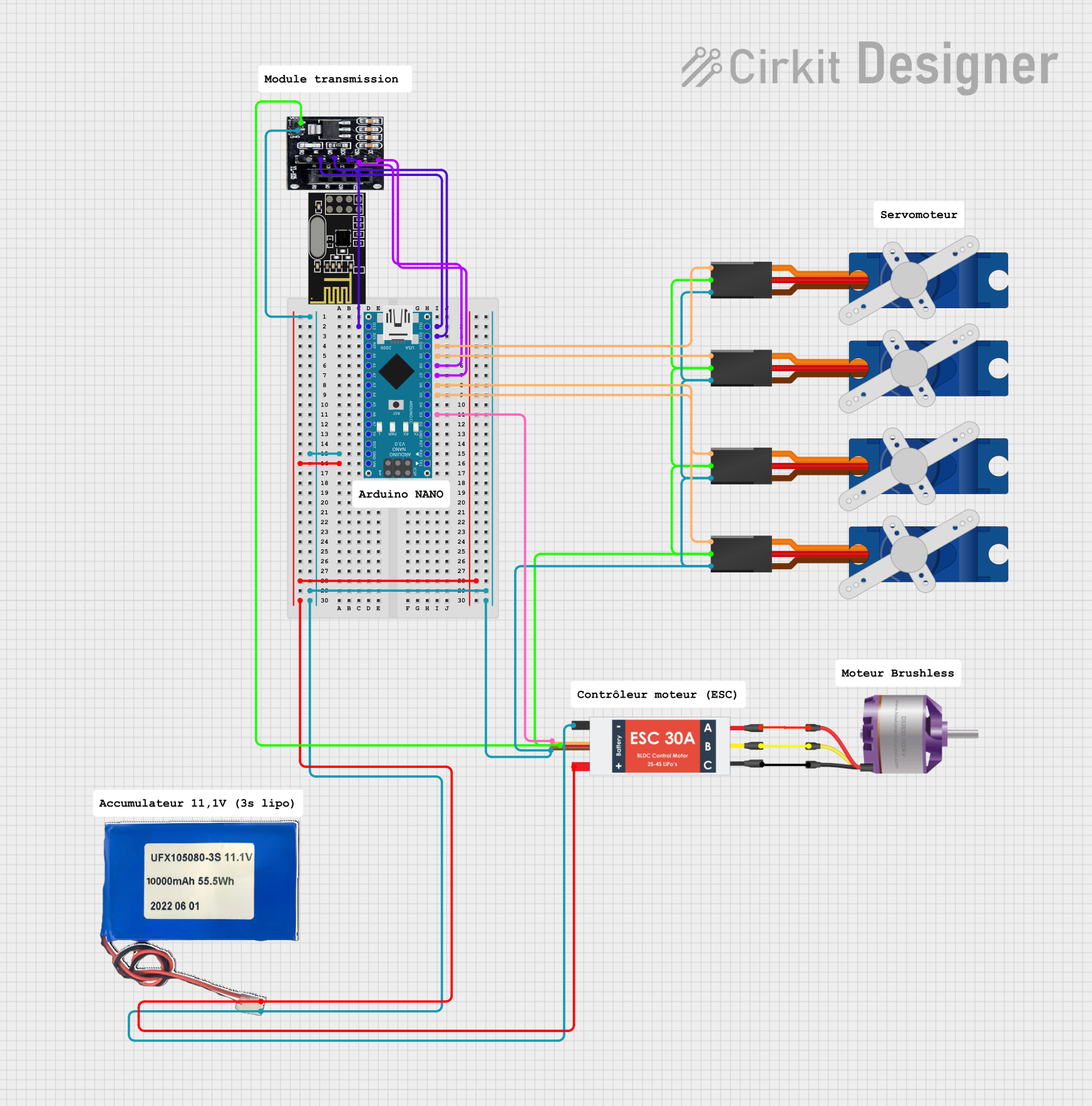
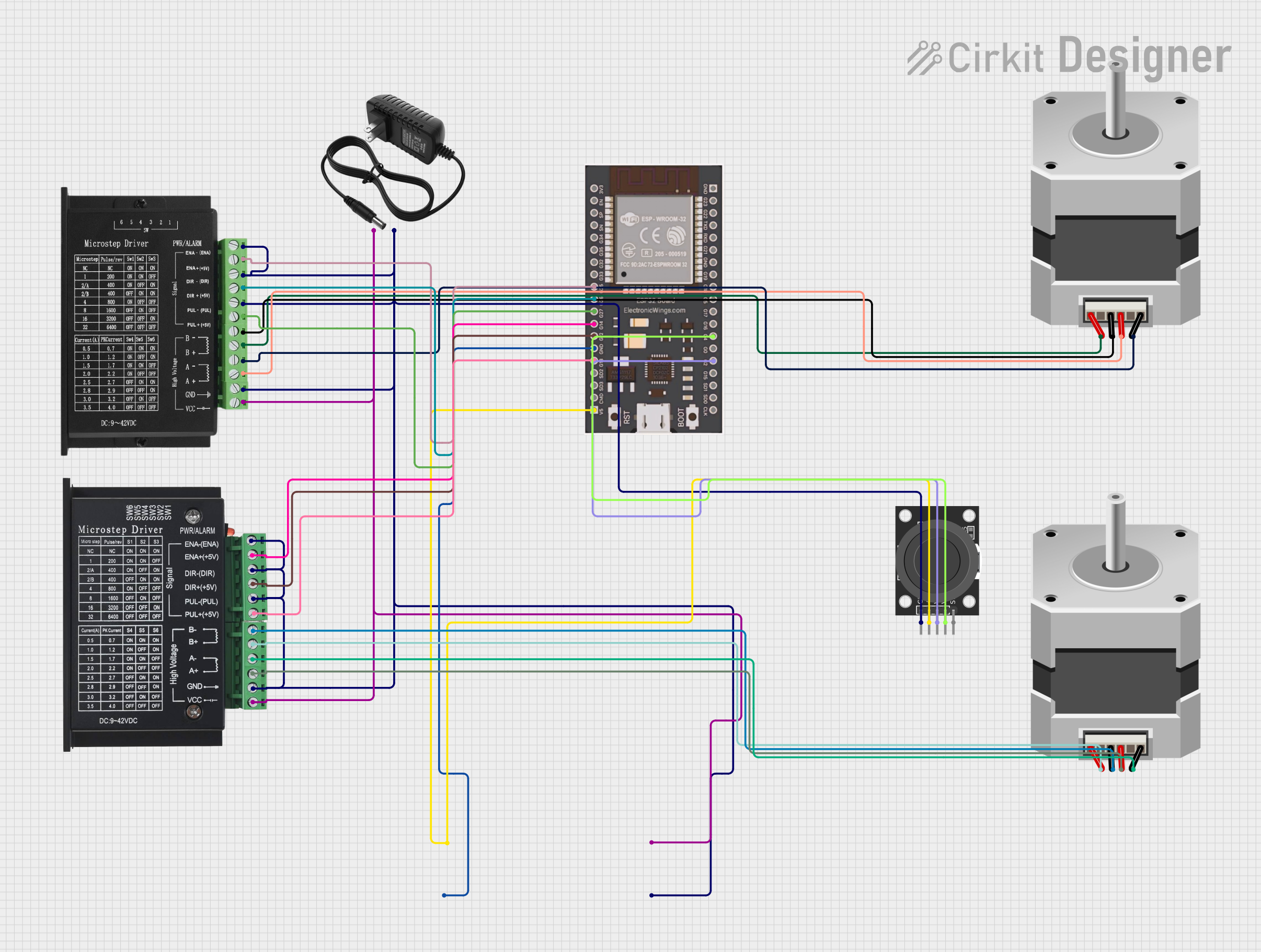
Explore Projects Built with xt90e
Common Applications and Use Cases
- RC vehicles (cars, boats, drones, and planes)
- Electric bikes and scooters
- High-power battery packs
- Solar power systems
- Robotics and industrial equipment
Technical Specifications
The XT90E connector is designed to handle high currents and provide a secure, low-resistance connection. Below are the key technical details:
| Parameter | Specification |
|---|---|
| Rated Current | 90A continuous |
| Peak Current | 120A (short duration) |
| Voltage Rating | Up to 500V DC |
| Contact Resistance | ≤ 0.6 mΩ |
| Operating Temperature | -20°C to 120°C |
| Connector Material | Nylon (high-temperature resistant) |
| Contact Material | Gold-plated copper |
| Dimensions (assembled) | 21.5mm x 29mm x 8.5mm |
| Weight | ~7g per connector |
Pin Configuration and Descriptions
The XT90E connector consists of two main terminals: positive (+) and negative (-). These terminals are clearly marked on the connector housing to prevent incorrect connections.
| Pin | Description |
|---|---|
| Positive | Connects to the positive terminal of the power source or load. |
| Negative | Connects to the negative terminal of the power source or load. |
Usage Instructions
How to Use the XT90E in a Circuit
Soldering the Wires:
- Strip the insulation from the wires to expose approximately 5mm of copper.
- Tin the exposed wire ends with solder to ensure a strong connection.
- Insert the tinned wire into the connector's solder cup and apply heat with a soldering iron until the solder flows evenly.
- Allow the connection to cool before proceeding.
Assembling the Connector:
- Once the wires are soldered, slide the connector housing over the terminals.
- Ensure the positive and negative terminals are correctly aligned with the housing markings.
Connecting to a Circuit:
- Plug the XT90E male and female connectors together until the locking mechanism clicks into place.
- Verify the connection is secure and that there is no exposed wiring.
Important Considerations and Best Practices
- Wire Gauge: Use appropriately sized wires (e.g., 10-12 AWG) to handle the current without overheating.
- Soldering Temperature: Use a soldering iron with sufficient power (60W or higher) to ensure proper soldering of the high-current terminals.
- Polarity: Double-check the polarity markings on the connector to avoid reverse connections, which can damage your circuit.
- Heat Shrink Tubing: Use heat shrink tubing over the soldered connections for added insulation and strain relief.
- Mating Cycles: The XT90E is rated for multiple mating cycles, but excessive wear or dirt can degrade performance. Clean the connectors periodically.
Example: Connecting XT90E to an Arduino UNO Power Supply
While the XT90E is not directly used with low-power devices like the Arduino UNO, it can be part of a power delivery system. For example, you can use an XT90E connector to connect a high-capacity battery to a voltage regulator, which then powers the Arduino UNO.
// Example: Reading battery voltage from a high-power XT90E-connected battery
// connected to a voltage divider circuit on an Arduino UNO.

const int batteryPin = A0;  // Analog pin connected to the voltage divider
float voltage = 0.0;        // Variable to store the calculated voltage

void setup() {
  Serial.begin(9600);  // Initialize serial communication
}

void loop() {
  int sensorValue = analogRead(batteryPin);  // Read the analog input
  voltage = sensorValue * (5.0 / 1023.0) * 11;
  // Convert the analog reading to voltage. The multiplier (11) assumes a
  // voltage divider with a 10:1 ratio for high-voltage measurement.

  Serial.print("Battery Voltage: ");
  Serial.print(voltage);
  Serial.println(" V");

  delay(1000);  // Wait for 1 second before the next reading
}
Troubleshooting and FAQs
Common Issues and Solutions
| Issue | Solution |
|---|---|
| Connector does not fit securely | Ensure the male and female connectors are properly aligned and free of debris. |
| Overheating during operation | Check for loose connections or undersized wires. Use wires with appropriate gauge. |
| Difficulty soldering wires to terminals | Use a high-power soldering iron (60W or higher) and pre-tin the wires and terminals. |
| Reverse polarity connection | Always verify the polarity markings on the connector before connecting. |
FAQs
Can the XT90E handle currents above 90A?
- Yes, the XT90E can handle peak currents of up to 120A for short durations. However, for continuous operation, it is recommended to stay within the 90A rating.
Is the XT90E waterproof?
- No, the XT90E is not waterproof. If used in outdoor or wet environments, additional waterproofing measures (e.g., heat shrink tubing or silicone sealant) are recommended.
Can I use the XT90E with smaller wires?
- While it is possible, using smaller wires may result in overheating and increased resistance. It is best to use wires that match the current requirements of your application.
How many mating cycles can the XT90E handle?
- The XT90E is rated for approximately 100 mating cycles. Regular inspection and cleaning can help maintain performance over time.
By following these guidelines and best practices, the XT90E can provide a reliable and efficient connection for your high-power applications.