How to Use esp32: Examples, Pinouts, and Specs
Introduction
The ESP32 is a low-cost, low-power system on a chip (SoC) developed by Espressif Systems. It features integrated Wi-Fi and Bluetooth capabilities, making it an ideal choice for Internet of Things (IoT) applications, smart devices, and embedded systems. The ESP32 is highly versatile, offering dual-core processing, a wide range of GPIO pins, and support for various communication protocols.
Explore Projects Built with esp32


Explore Projects Built with esp32
Common Applications and Use Cases
- IoT devices (e.g., smart home systems, sensors, and actuators)
- Wearable technology
- Wireless communication hubs
- Robotics and automation
- Data logging and remote monitoring
- Prototyping and development of connected devices
Technical Specifications
The ESP32 is packed with features that make it a powerful and flexible component for a wide range of applications. Below are its key technical specifications:
Key Technical Details
- Processor: Dual-core Xtensa® 32-bit LX6 microprocessor
- Clock Speed: Up to 240 MHz
- RAM: 520 KB SRAM
- Flash Memory: Typically 4 MB (varies by module)
- Wi-Fi: 802.11 b/g/n (2.4 GHz)
- Bluetooth: v4.2 BR/EDR and BLE
- Operating Voltage: 3.0V to 3.6V
- GPIO Pins: 34 (multipurpose, including ADC, DAC, PWM, I2C, SPI, UART)
- ADC Resolution: 12-bit
- DAC Resolution: 8-bit
- Power Consumption: Ultra-low power modes available (as low as 5 µA in deep sleep)
- Temperature Range: -40°C to 125°C
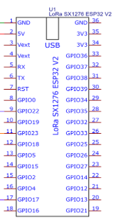
Pin Configuration and Descriptions
The ESP32 has a variety of pins for different functionalities. Below is a table summarizing the most commonly used pins:
| Pin Name | Function | Description |
|---|---|---|
| GPIO0 | Input/Output, Boot Mode Select | Used for boot mode selection during startup. |
| GPIO2 | Input/Output, ADC, DAC | General-purpose pin, supports ADC and DAC. |
| GPIO12 | Input/Output, ADC | General-purpose pin, supports ADC. |
| GPIO13 | Input/Output, PWM, ADC | General-purpose pin, supports PWM and ADC. |
| GPIO15 | Input/Output, ADC | General-purpose pin, supports ADC. |
| GPIO16 | Input/Output | General-purpose pin. |
| GPIO17 | Input/Output | General-purpose pin. |
| EN | Enable | Active-high enable pin to reset the chip. |
| 3V3 | Power | 3.3V power supply input/output. |
| GND | Ground | Ground connection. |
| TX0 (GPIO1) | UART Transmit | UART0 transmit pin for serial communication. |
| RX0 (GPIO3) | UART Receive | UART0 receive pin for serial communication. |
Note: The exact pinout may vary depending on the ESP32 module or development board (e.g., ESP32-WROOM-32, ESP32-WROVER).
Usage Instructions
The ESP32 can be used in a variety of circuits and projects. Below are the steps to get started and some best practices to follow.
How to Use the ESP32 in a Circuit
Powering the ESP32:
- Connect the 3.3V pin to a stable 3.3V power source.
- Ensure the GND pin is connected to the ground of the circuit.
- If using a development board (e.g., ESP32 DevKit), you can power it via the USB port.
Programming the ESP32:
- Install the Arduino IDE or ESP-IDF (Espressif IoT Development Framework).
- Add the ESP32 board support to the Arduino IDE by including the appropriate URL in the Board Manager.
- Connect the ESP32 to your computer via USB and select the correct board and port in the IDE.
Connecting Peripherals:
- Use GPIO pins to connect sensors, actuators, or other peripherals.
- Configure the pins in your code according to the desired functionality (e.g., input, output, ADC, PWM).
Uploading Code:
- Write your program in the Arduino IDE or ESP-IDF.
- Compile and upload the code to the ESP32.
- Monitor the serial output for debugging or feedback.
Example Code for Arduino IDE
Below is an example of how to blink an LED connected to GPIO2 of the ESP32:
// Define the GPIO pin for the LED
#define LED_PIN 2

void setup() {
  // Set the LED pin as an output
  pinMode(LED_PIN, OUTPUT);
}

void loop() {
  // Turn the LED on
  digitalWrite(LED_PIN, HIGH);
  delay(1000); // Wait for 1 second

  // Turn the LED off
  digitalWrite(LED_PIN, LOW);
  delay(1000); // Wait for 1 second
}
Important Considerations and Best Practices
- Voltage Levels: The ESP32 operates at 3.3V. Avoid applying 5V to its GPIO pins to prevent damage.
- Power Supply: Use a stable power source to avoid unexpected resets or instability.
- Boot Mode: Ensure GPIO0 is pulled low during boot to enter programming mode.
- Deep Sleep: Use the deep sleep mode to conserve power in battery-powered applications.
- Heat Management: If the ESP32 operates at high loads, consider adding a heatsink or ensuring proper ventilation.
Troubleshooting and FAQs
Common Issues and Solutions
ESP32 Not Detected by Computer:
- Ensure the correct USB driver is installed (e.g., CP210x or CH340).
- Check the USB cable for data transfer capability (some cables are power-only).
Code Upload Fails:
- Verify that GPIO0 is pulled low during programming.
- Check the selected board and port in the Arduino IDE.
- Press and hold the "BOOT" button on the ESP32 board while uploading.
Wi-Fi Connection Issues:
- Double-check the SSID and password in your code.
- Ensure the Wi-Fi network is within range and not using unsupported security protocols.
Random Resets or Instability:
- Use a stable power supply with sufficient current (at least 500 mA).
- Check for loose connections or short circuits in the circuit.
FAQs
Q: Can the ESP32 be powered with 5V?
A: The ESP32 itself operates at 3.3V, but many development boards include a voltage regulator that allows them to be powered with 5V via the USB port or VIN pin.
Q: How do I use the Bluetooth functionality?
A: The ESP32 supports both Bluetooth Classic and BLE. You can use libraries like BluetoothSerial (for Classic) or BLEDevice (for BLE) in the Arduino IDE.
Q: What is the maximum range of the ESP32's Wi-Fi?
A: The range depends on the environment but is typically around 50 meters indoors and up to 200 meters outdoors with a clear line of sight.
Q: Can I use the ESP32 with a battery?
A: Yes, the ESP32 can be powered by a battery. Use a 3.7V LiPo battery with a voltage regulator or a battery management module for safe operation.
Q: How do I reset the ESP32?
A: Press the "EN" (Enable) button on the development board to reset the ESP32.
By following this documentation, you can effectively integrate the ESP32 into your projects and troubleshoot common issues.