Cirkit Designer Logo
Cirkit Designer
Your all-in-one circuit design IDE
Home / 
Component Documentation

How to Use kit mini ups: Examples, Pinouts, and Specs

Image of kit mini ups
Cirkit Designer LogoDesign with kit mini ups in Cirkit Designer

Introduction

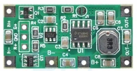
The Kit Mini UPS is a compact uninterruptible power supply designed to provide backup power to electronic devices during power outages. It ensures continuous operation, protects against data loss, and safeguards sensitive equipment from sudden power interruptions. Its small form factor makes it ideal for use with routers, modems, IoT devices, and other low-power electronics.

Explore Projects Built with kit mini ups

Use Cirkit Designer to design, explore, and prototype these projects online. Some projects support real-time simulation. Click "Open Project" to start designing instantly!
12V UPS System with Dual 18650 Li-ion Battery Backup and Voltage Regulation
Image of Power supply: A project utilizing kit mini ups in a practical application
This circuit is designed to provide an uninterruptible power supply (UPS) system with a 12V DC output. It includes a 12V 5A power supply connected to an AC source through a toggle switch, which charges a pair of 18650 Li-ion batteries via a voltage regulator (XL4016). The UPS module ensures a continuous power supply to the load by switching between the power supply and the battery bank.
Cirkit Designer LogoOpen Project in Cirkit Designer
Battery-Powered UPS with Step-Down Buck Converter and BMS
Image of Mini ups: A project utilizing kit mini ups in a practical application
This circuit is a power management system that steps down a 240V AC input to a lower DC voltage using a buck converter, which then powers a 40W UPS. The UPS is controlled by a rocker switch and is backed up by a battery management system (BMS) connected to three 3.7V batteries in series, ensuring continuous power supply.
Cirkit Designer LogoOpen Project in Cirkit Designer
ESP32-S3 Battery-Powered Environmental Monitoring System with OLED Display
Image of Diagram wiring: A project utilizing kit mini ups in a practical application
This circuit is a sensor and display system powered by a UPS module with a 12V power supply and 18650 batteries. It includes an ESP32 microcontroller that interfaces with various sensors (DHT22, Strain Gauge, MPU-6050, ADXL345) and an OLED display, with power regulation provided by a step-down buck converter.
Cirkit Designer LogoOpen Project in Cirkit Designer
ESP32-S3 Based Vibration Detection System with TFT Display and Power Backup
Image of IOT Thesis: A project utilizing kit mini ups in a practical application
This circuit features an ESP32-S3 microcontroller connected to various peripherals including an ADXL355 accelerometer, an SW-420 vibration sensor, a buzzer module, and an ILI9341 TFT display. The ESP32-S3 manages sensor inputs and provides output to the display and buzzer. Power management is handled by a 12V to 5V step-down converter, and a UPS ensures uninterrupted power supply, with a rocker switch to control the power flow.
Cirkit Designer LogoOpen Project in Cirkit Designer

Explore Projects Built with kit mini ups

Use Cirkit Designer to design, explore, and prototype these projects online. Some projects support real-time simulation. Click "Open Project" to start designing instantly!
Image of Power supply: A project utilizing kit mini ups in a practical application
12V UPS System with Dual 18650 Li-ion Battery Backup and Voltage Regulation
This circuit is designed to provide an uninterruptible power supply (UPS) system with a 12V DC output. It includes a 12V 5A power supply connected to an AC source through a toggle switch, which charges a pair of 18650 Li-ion batteries via a voltage regulator (XL4016). The UPS module ensures a continuous power supply to the load by switching between the power supply and the battery bank.
Cirkit Designer LogoOpen Project in Cirkit Designer
Image of Mini ups: A project utilizing kit mini ups in a practical application
Battery-Powered UPS with Step-Down Buck Converter and BMS
This circuit is a power management system that steps down a 240V AC input to a lower DC voltage using a buck converter, which then powers a 40W UPS. The UPS is controlled by a rocker switch and is backed up by a battery management system (BMS) connected to three 3.7V batteries in series, ensuring continuous power supply.
Cirkit Designer LogoOpen Project in Cirkit Designer
Image of Diagram wiring: A project utilizing kit mini ups in a practical application
ESP32-S3 Battery-Powered Environmental Monitoring System with OLED Display
This circuit is a sensor and display system powered by a UPS module with a 12V power supply and 18650 batteries. It includes an ESP32 microcontroller that interfaces with various sensors (DHT22, Strain Gauge, MPU-6050, ADXL345) and an OLED display, with power regulation provided by a step-down buck converter.
Cirkit Designer LogoOpen Project in Cirkit Designer
Image of IOT Thesis: A project utilizing kit mini ups in a practical application
ESP32-S3 Based Vibration Detection System with TFT Display and Power Backup
This circuit features an ESP32-S3 microcontroller connected to various peripherals including an ADXL355 accelerometer, an SW-420 vibration sensor, a buzzer module, and an ILI9341 TFT display. The ESP32-S3 manages sensor inputs and provides output to the display and buzzer. Power management is handled by a 12V to 5V step-down converter, and a UPS ensures uninterrupted power supply, with a rocker switch to control the power flow.
Cirkit Designer LogoOpen Project in Cirkit Designer

Common Applications and Use Cases

  • Providing backup power to Wi-Fi routers and modems to maintain internet connectivity during outages.
  • Powering IoT devices, such as smart home hubs and sensors, during power interruptions.
  • Protecting small electronic devices from sudden power loss and voltage fluctuations.
  • Ensuring uninterrupted operation of security cameras and surveillance systems.

Technical Specifications

The Kit Mini UPS is designed to deliver reliable performance for low-power devices. Below are its key technical specifications:

Parameter Value
Input Voltage 12V DC
Output Voltage 12V DC (regulated)
Output Current Up to 2A
Battery Type Lithium-ion
Battery Capacity 2600mAh (typical)
Charging Time 4-6 hours
Backup Time 2-4 hours (depending on load)
Protection Features Overcharge, over-discharge, short circuit
Dimensions 100mm x 60mm x 25mm
Weight 150g

Pin Configuration and Descriptions

The Kit Mini UPS typically has the following connectors:

Connector Description
Input Port 12V DC input for charging the UPS.
Output Port 12V DC output to power connected devices.
LED Indicator Displays the status of the UPS (charging, discharging, etc.).

Usage Instructions

How to Use the Kit Mini UPS in a Circuit

  1. Connect the Input Port: Plug a 12V DC adapter into the input port of the Kit Mini UPS to charge the internal battery.
  2. Connect the Output Port: Use the output port to power your device. Ensure the device operates at 12V DC and does not exceed the 2A current limit.
  3. Monitor the LED Indicator: The LED indicator will show the status of the UPS:
    • Green Light: Fully charged and operational.
    • Red Light: Charging in progress.
    • Blinking Light: Low battery or fault condition.

Important Considerations and Best Practices

  • Verify Compatibility: Ensure the connected device operates at 12V DC and does not draw more than 2A of current.
  • Avoid Overloading: Connecting devices that exceed the UPS's current rating may cause it to shut down or fail.
  • Charge Regularly: To maintain battery health, charge the UPS at least once every three months if not in regular use.
  • Ventilation: Place the UPS in a well-ventilated area to prevent overheating during operation.

Example: Using the Kit Mini UPS with an Arduino UNO

The Kit Mini UPS can be used to power an Arduino UNO during power outages. Below is an example setup:

  1. Connect the output port of the Kit Mini UPS to the Arduino UNO's DC barrel jack.
  2. Ensure the UPS is fully charged before use.
  3. The Arduino UNO will continue to operate seamlessly during power interruptions.

Here is a simple Arduino sketch to demonstrate functionality:

// Example code to blink an LED on pin 13
// This code ensures the Arduino remains operational during power outages
// when powered by the Kit Mini UPS.

void setup() {
  pinMode(13, OUTPUT); // Set pin 13 as an output pin
}

void loop() {
  digitalWrite(13, HIGH); // Turn the LED on
  delay(1000);            // Wait for 1 second
  digitalWrite(13, LOW);  // Turn the LED off
  delay(1000);            // Wait for 1 second
}

Troubleshooting and FAQs

Common Issues and Solutions

  1. The UPS is not charging.

    • Solution: Check the input adapter and ensure it provides 12V DC. Verify the connection to the input port.
  2. The connected device does not power on.

    • Solution: Ensure the device operates at 12V DC and does not exceed the 2A current limit. Check the battery charge level.
  3. The UPS shuts down unexpectedly.

    • Solution: This may occur due to overloading. Disconnect the device and verify its power requirements.
  4. The LED indicator is blinking continuously.

    • Solution: This indicates a low battery or fault condition. Charge the UPS fully and check for any short circuits.

FAQs

  1. Can the Kit Mini UPS be used with devices other than routers?

    • Yes, it can power any 12V DC device within the 2A current limit.
  2. How long does the UPS provide backup power?

    • The backup time ranges from 2 to 4 hours, depending on the power consumption of the connected device.
  3. Is the UPS safe to use with sensitive electronics?

    • Yes, it includes protection features such as overcharge, over-discharge, and short circuit protection to ensure safe operation.
  4. Can the battery be replaced?

    • The battery is not user-replaceable. Contact the manufacturer for service or replacement options.

By following this documentation, you can effectively use the Kit Mini UPS to ensure uninterrupted power for your devices.