How to Use Arduino MKR WAN 1310: Examples, Pinouts, and Specs
Introduction
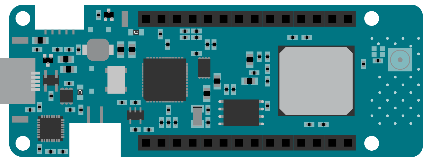
The Arduino MKR WAN 1310 is a microcontroller board specifically designed for Internet of Things (IoT) applications. It features LoRa® connectivity, enabling long-range, low-power communication, and is powered by the SAMD21 Cortex-M0+ 32-bit ARM microcontroller. Its compact form factor and versatile features make it ideal for projects requiring efficient data transmission over long distances, such as environmental monitoring, smart agriculture, and industrial IoT systems.
Explore Projects Built with Arduino MKR WAN 1310
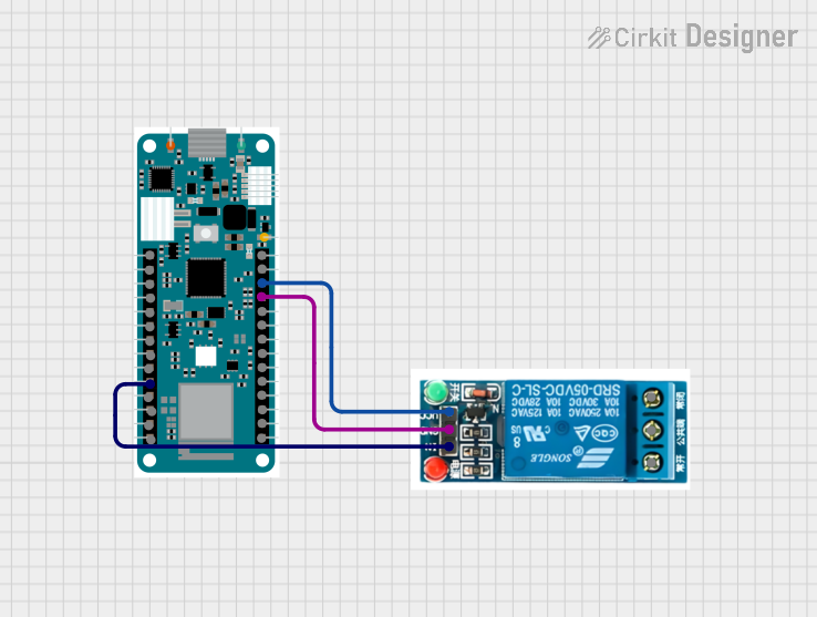
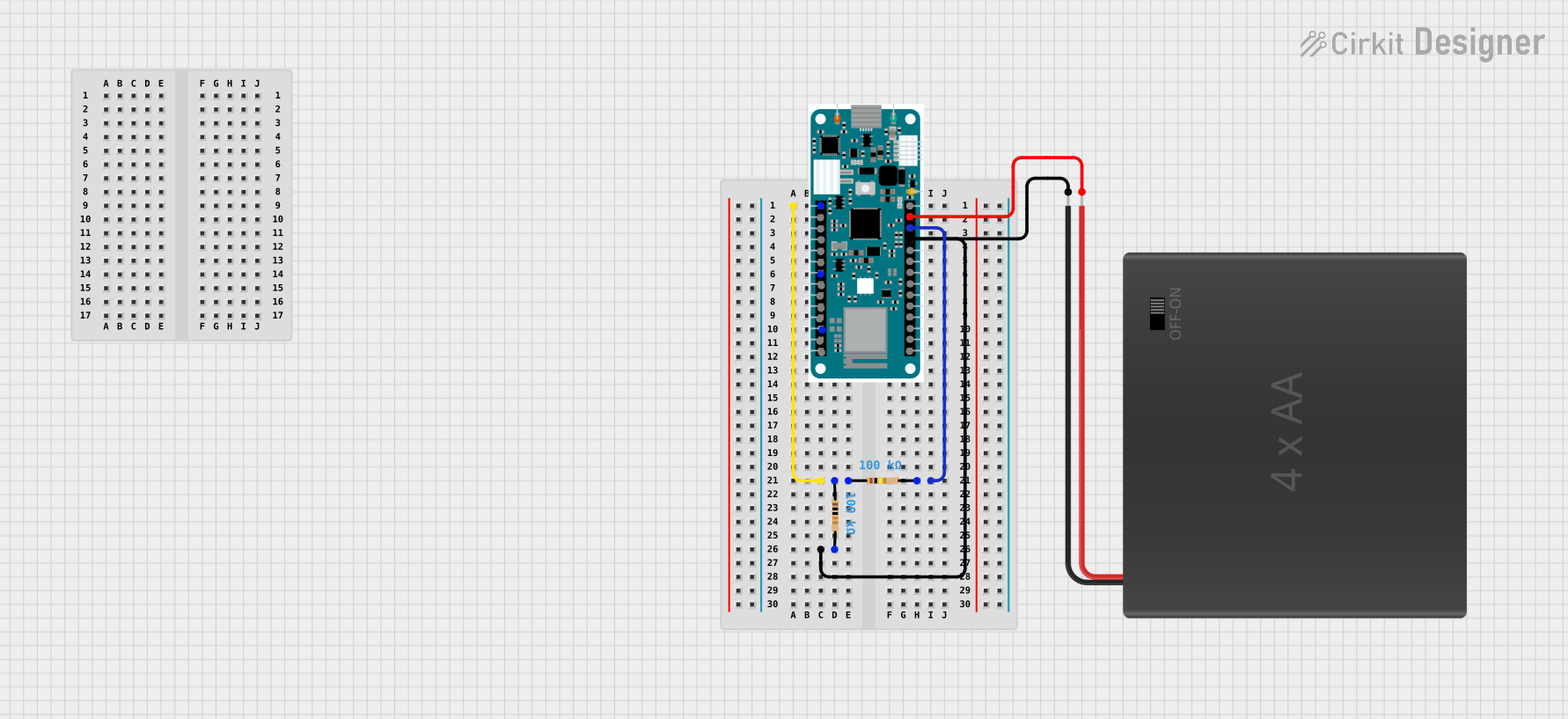
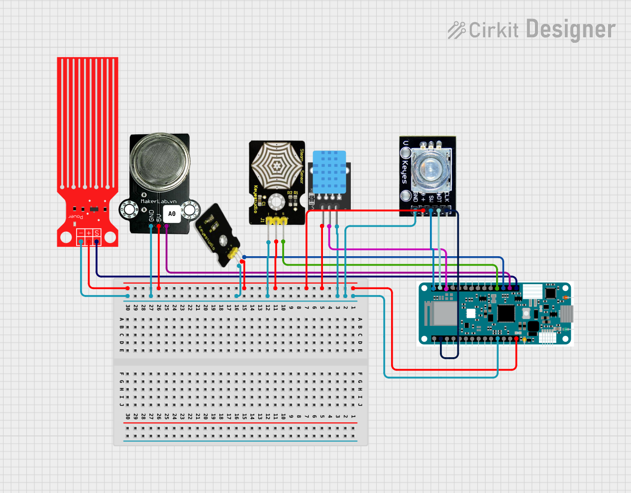
Explore Projects Built with Arduino MKR WAN 1310
Common Applications and Use Cases
- Smart agriculture (e.g., soil moisture monitoring, weather stations)
- Environmental monitoring (e.g., air quality sensors, water level monitoring)
- Industrial IoT (e.g., asset tracking, predictive maintenance)
- Smart cities (e.g., parking sensors, waste management systems)
- Home automation (e.g., remote control of devices, energy monitoring)
Technical Specifications
The Arduino MKR WAN 1310 combines powerful hardware with LoRa® connectivity to meet the demands of IoT applications. Below are its key technical details:
Key Technical Details
| Specification | Value |
|---|---|
| Microcontroller | SAMD21 Cortex-M0+ 32-bit ARM |
| LoRa® Module | Murata CMWX1ZZABZ (SX1276) |
| Operating Voltage | 3.3V |
| Input Voltage (via VIN pin) | 5V to 12V |
| Digital I/O Pins | 8 |
| PWM Pins | 12 |
| Analog Input Pins | 7 (12-bit ADC) |
| Flash Memory | 256 KB |
| SRAM | 32 KB |
| EEPROM | None |
| Clock Speed | 48 MHz |
| Communication Interfaces | UART, I2C, SPI |
| Battery Connector | JST 2-pin for Li-Po battery (3.7V) |
| Dimensions | 67.64 mm x 25 mm |
| Weight | 32 g |
Pin Configuration and Descriptions
The MKR WAN 1310 has a compact pinout designed for versatility. Below is the pin configuration:
| Pin Number | Pin Name | Description |
|---|---|---|
| 1 | VIN | Input voltage (5V to 12V) |
| 2 | 3.3V | Regulated 3.3V output |
| 3 | GND | Ground |
| 4 | A0 to A6 | Analog input pins (12-bit ADC) |
| 5 | D0 to D7 | Digital I/O pins |
| 6 | PWM Pins | Digital pins with PWM capability |
| 7 | I2C (SDA, SCL) | I2C communication pins |
| 8 | SPI (MISO, MOSI, SCK) | SPI communication pins |
| 9 | UART (TX, RX) | Serial communication pins |
| 10 | RESET | Reset the board |
| 11 | Li-Po Battery | JST connector for 3.7V Li-Po battery |
Usage Instructions
The Arduino MKR WAN 1310 is easy to integrate into IoT projects. Below are the steps to use it effectively:
How to Use the Component in a Circuit
Powering the Board:
- Connect a 5V to 12V power source to the VIN pin or use a 3.7V Li-Po battery via the JST connector.
- Alternatively, power the board via the micro-USB port.
Connecting Sensors and Actuators:
- Use the analog pins (A0 to A6) for sensors requiring analog input.
- Use the digital pins (D0 to D7) for digital sensors or actuators.
- For PWM control (e.g., dimming LEDs or controlling motors), use the PWM-capable pins.
LoRa® Communication:
- Configure the LoRa® module using the Arduino LoRa library.
- Ensure the antenna is securely connected to the board for optimal signal strength.
Programming the Board:
- Connect the board to your computer via the micro-USB cable.
- Open the Arduino IDE, select the correct board ("Arduino MKR WAN 1310"), and the appropriate COM port.
- Write or upload your sketch to the board.
Important Considerations and Best Practices
- Power Supply: Always ensure the input voltage is within the specified range to avoid damaging the board.
- Battery Usage: If using a Li-Po battery, monitor its charge level to prevent over-discharge.
- Antenna Connection: Always connect the LoRa® antenna before powering the board to avoid damaging the LoRa® module.
- Libraries: Install the required libraries (e.g.,
LoRa.h) in the Arduino IDE for LoRa® communication. - Environmental Conditions: Operate the board within the recommended temperature range (-40°C to 85°C).
Example Code for LoRa® Communication
Below is an example of how to send a simple message using the LoRa® module:
#include <LoRa.h> // Include the LoRa library

void setup() {
  Serial.begin(9600); // Initialize serial communication
  while (!Serial);

  Serial.println("Initializing LoRa...");

  // Initialize LoRa module with frequency (e.g., 915E6 for 915 MHz)
  if (!LoRa.begin(915E6)) {
    Serial.println("LoRa initialization failed!");
    while (1);
  }

  Serial.println("LoRa initialized successfully!");
}

void loop() {
  Serial.println("Sending message...");

  // Begin LoRa packet
  LoRa.beginPacket();
  LoRa.print("Hello, LoRa!"); // Add message to the packet
  LoRa.endPacket(); // Send the packet

  delay(5000); // Wait 5 seconds before sending the next message
}
Troubleshooting and FAQs
Common Issues and Solutions
LoRa® Module Not Initializing:
- Cause: Incorrect frequency or antenna not connected.
- Solution: Verify the frequency matches your region's regulations (e.g., 915 MHz for the US, 868 MHz for Europe). Ensure the antenna is securely connected.
Board Not Detected by Arduino IDE:
- Cause: Missing drivers or incorrect COM port selected.
- Solution: Install the latest Arduino SAMD board package in the Arduino IDE. Check the COM port in the "Tools" menu.
Low Signal Strength:
- Cause: Poor antenna placement or interference.
- Solution: Place the antenna in an open area, away from metal objects or other sources of interference.
Battery Draining Quickly:
- Cause: High power consumption or faulty battery.
- Solution: Use sleep modes in your code to reduce power consumption. Check the battery health.
FAQs
Q: Can I use the MKR WAN 1310 without a battery?
A: Yes, the board can be powered via the micro-USB port or the VIN pin without a battery.
Q: What is the maximum range of the LoRa® module?
A: The range depends on environmental factors but can reach up to 10 km in open areas.
Q: Is the MKR WAN 1310 compatible with other Arduino shields?
A: Yes, it is compatible with MKR form-factor shields.
Q: How do I update the firmware of the LoRa® module?
A: Firmware updates can be performed using the Arduino IDE and the appropriate libraries. Refer to the official Arduino documentation for detailed instructions.