How to Use Lamps & Buzzer: Examples, Pinouts, and Specs
Introduction
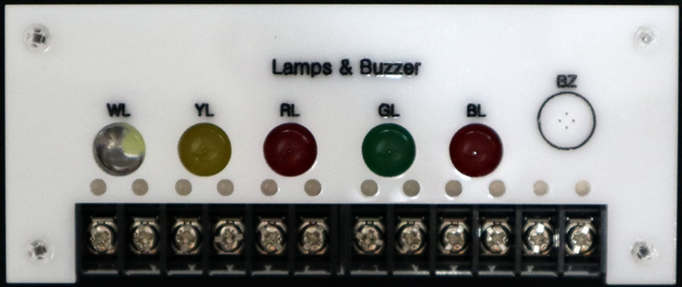
The Lamps & Buzzer module, manufactured by Cirkit (Part ID: Lamps & Buzzer), is a versatile electronic component designed for visual and auditory signaling in various applications. This module combines a lamp (LED or incandescent) for visual indication and a buzzer for sound-based alerts, making it ideal for systems requiring dual-mode notifications.
Explore Projects Built with Lamps & Buzzer
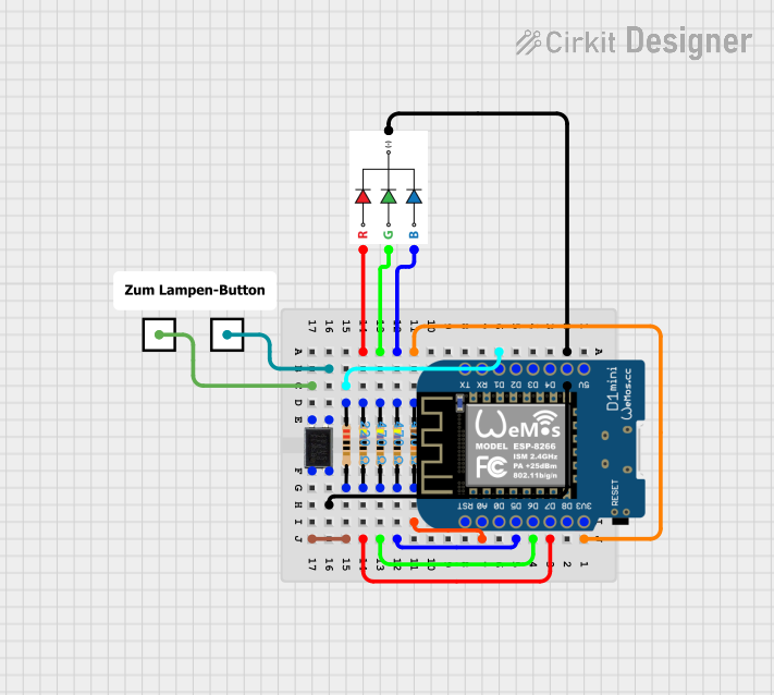

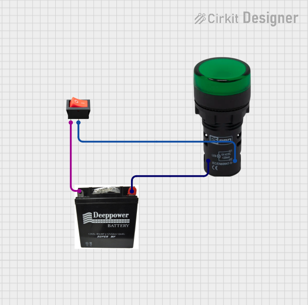

Explore Projects Built with Lamps & Buzzer
Common Applications and Use Cases
- Alarm systems (e.g., fire alarms, security systems)
- Status indicators in industrial equipment
- Educational projects and prototyping
- Arduino-based DIY projects
- Automotive signaling systems
Technical Specifications
Key Technical Details
| Parameter | Specification |
|---|---|
| Operating Voltage | 3V to 12V (DC) |
| Current Consumption | Lamp: 20mA (typical), Buzzer: 30mA |
| Buzzer Frequency | 2 kHz to 4 kHz |
| Lamp Type | LED or Miniature Incandescent |
| Operating Temperature | -20°C to +70°C |
| Dimensions | 30mm x 20mm x 15mm |
Pin Configuration and Descriptions
| Pin Number | Pin Name | Description |
|---|---|---|
| 1 | VCC | Positive power supply (3V to 12V DC) |
| 2 | GND | Ground connection |
| 3 | Lamp Signal | Input signal to activate the lamp |
| 4 | Buzzer Signal | Input signal to activate the buzzer |
Usage Instructions
How to Use the Component in a Circuit
- Power Supply: Connect the
VCCpin to a DC power source (3V to 12V) and theGNDpin to the ground of the circuit. - Lamp Activation: Apply a HIGH signal (logic 1) to the
Lamp Signalpin to turn on the lamp. Ensure the input voltage matches the operating voltage of the lamp. - Buzzer Activation: Apply a HIGH signal (logic 1) to the
Buzzer Signalpin to activate the buzzer. The buzzer will emit a sound at its rated frequency. - Simultaneous Operation: Both the lamp and buzzer can be activated simultaneously by applying HIGH signals to their respective input pins.
Important Considerations and Best Practices
- Voltage Compatibility: Ensure the input voltage does not exceed the specified range (3V to 12V) to avoid damage.
- Current Limiting: Use a current-limiting resistor for the lamp if it is an LED to prevent overcurrent.
- Signal Timing: For pulsed signals, ensure the duty cycle and frequency are within the component's operating range.
- Heat Dissipation: Avoid prolonged activation of the lamp or buzzer at maximum voltage to prevent overheating.
Example: Connecting to an Arduino UNO
Below is an example of how to connect and control the Lamps & Buzzer module using an Arduino UNO:
Circuit Connections
- Connect the
VCCpin of the module to the 5V pin on the Arduino. - Connect the
GNDpin of the module to the GND pin on the Arduino. - Connect the
Lamp Signalpin to digital pin 8 on the Arduino. - Connect the
Buzzer Signalpin to digital pin 9 on the Arduino.
Arduino Code
// Lamps & Buzzer Control Example
// This code demonstrates how to control the lamp and buzzer using an Arduino UNO.

#define LAMP_PIN 8    // Pin connected to the Lamp Signal
#define BUZZER_PIN 9  // Pin connected to the Buzzer Signal

void setup() {
  pinMode(LAMP_PIN, OUTPUT);   // Set Lamp Signal pin as output
  pinMode(BUZZER_PIN, OUTPUT); // Set Buzzer Signal pin as output
}

void loop() {
  digitalWrite(LAMP_PIN, HIGH);  // Turn on the lamp
  digitalWrite(BUZZER_PIN, HIGH); // Turn on the buzzer
  delay(1000);                   // Wait for 1 second

  digitalWrite(LAMP_PIN, LOW);   // Turn off the lamp
  digitalWrite(BUZZER_PIN, LOW); // Turn off the buzzer
  delay(1000);                   // Wait for 1 second
}
Troubleshooting and FAQs
Common Issues and Solutions
Lamp or Buzzer Not Activating:
- Cause: Incorrect wiring or insufficient power supply.
- Solution: Double-check the connections and ensure the power supply voltage is within the specified range.
Buzzer Produces Weak or No Sound:
- Cause: Input signal voltage is too low.
- Solution: Verify that the input signal voltage matches the operating voltage of the buzzer.
Lamp Flickering:
- Cause: Unstable power supply or loose connections.
- Solution: Use a stable DC power source and ensure all connections are secure.
Overheating:
- Cause: Prolonged operation at maximum voltage.
- Solution: Reduce the operating voltage or limit the activation duration.
FAQs
Q1: Can I use this module with a 3.3V microcontroller?
A1: Yes, the module is compatible with 3.3V systems, but ensure the input signals are within the operating voltage range.
Q2: Can the lamp and buzzer be controlled independently?
A2: Yes, the lamp and buzzer have separate input pins, allowing independent control.
Q3: What type of lamp is used in this module?
A3: The module typically uses an LED or a miniature incandescent lamp, depending on the variant.
Q4: Is the buzzer tone adjustable?
A4: No, the buzzer operates at a fixed frequency. For adjustable tones, consider using a PWM signal with a piezo buzzer.