
Cirkit Designer
Your all-in-one circuit design IDE
Home /
Component Documentation
How to Use VCC 3.3V: Examples, Pinouts, and Specs

 Design with VCC 3.3V in Cirkit Designer
Introduction
- The VCC 3.3V is a voltage supply that provides a constant output of 3.3 volts. It is widely used in digital circuits to power microcontrollers, sensors, and other low-voltage components.
- Common applications include powering devices like ESP8266, ESP32, and other 3.3V logic-level components, as well as interfacing with low-power sensors and modules.
Explore Projects Built with VCC 3.3V
Battery-Powered 18650 Li-ion Charger with USB Output and Adjustable Voltage Regulator

This circuit is a battery management and power supply system that uses three 3.7V batteries connected to a 3S 10A Li-ion 18650 Charger Protection Board Module for balanced charging and protection. The system includes a TP4056 Battery Charging Protection Module for additional charging safety, a Step Up Boost Power Converter to regulate and boost the voltage, and a USB regulator to provide a stable 5V output, controlled by a push switch.
Open Project in Cirkit DesignerESP32-Based Battery-Powered Multi-Sensor System
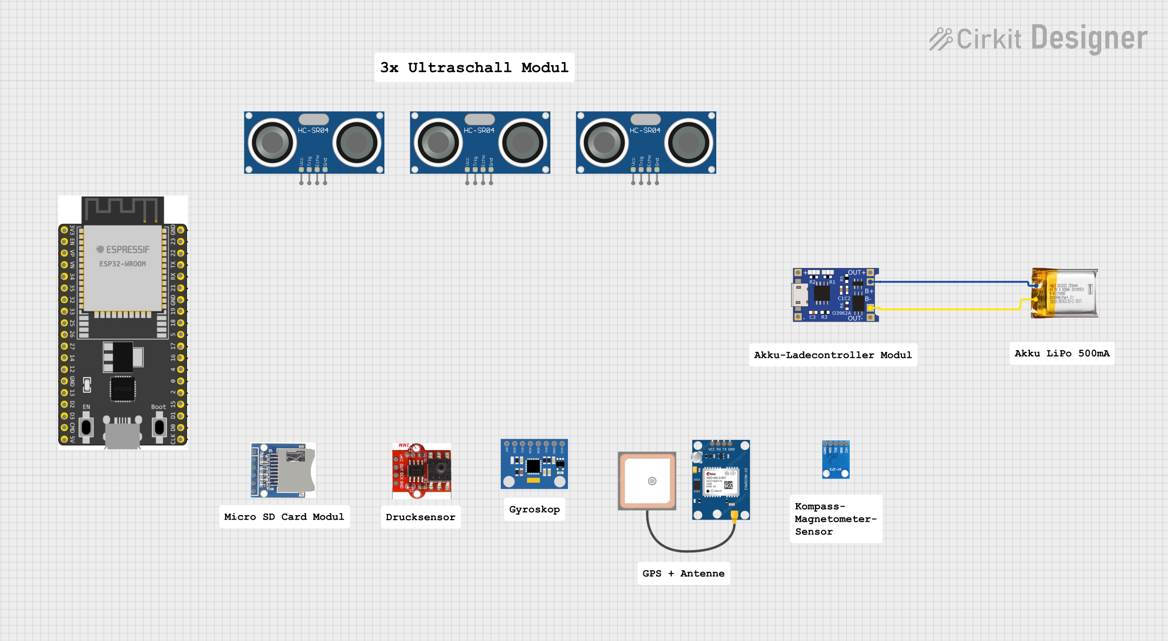
This circuit consists of a TP4056 module connected to a 3.7V LiPo battery, providing a charging interface for the battery. The TP4056 manages the charging process by connecting its B+ and B- pins to the battery's positive and ground terminals, respectively.
Open Project in Cirkit DesignerBattery-Powered Voltage Monitoring System with OLED Display using ATmega328P
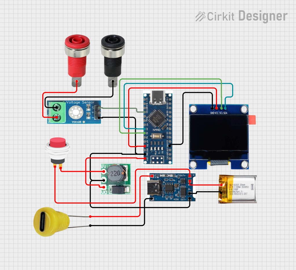
This circuit is a voltage monitoring and display system powered by a 3.7V LiPo battery. It uses an ATmega328P microcontroller to read voltage levels from a DC voltage sensor and displays the readings on a 1.3" OLED screen. The system includes a battery charger and a step-up boost converter to ensure stable operation and power management.
Open Project in Cirkit DesignerCellular-Enabled IoT Device with Real-Time Clock and Power Management

This circuit features a LilyGo-SIM7000G module for cellular communication and GPS functionality, interfaced with an RTC DS3231 for real-time clock capabilities. It includes voltage sensing through two voltage sensor modules, and uses an 8-channel opto-coupler for isolating different parts of the circuit. Power management is handled by a buck converter connected to a DC power source and batteries, with a fuse for protection and a rocker switch for on/off control. Additionally, there's an LED for indication purposes.
Open Project in Cirkit DesignerExplore Projects Built with VCC 3.3V
Battery-Powered 18650 Li-ion Charger with USB Output and Adjustable Voltage Regulator
This circuit is a battery management and power supply system that uses three 3.7V batteries connected to a 3S 10A Li-ion 18650 Charger Protection Board Module for balanced charging and protection. The system includes a TP4056 Battery Charging Protection Module for additional charging safety, a Step Up Boost Power Converter to regulate and boost the voltage, and a USB regulator to provide a stable 5V output, controlled by a push switch.
Open Project in Cirkit DesignerESP32-Based Battery-Powered Multi-Sensor System
This circuit consists of a TP4056 module connected to a 3.7V LiPo battery, providing a charging interface for the battery. The TP4056 manages the charging process by connecting its B+ and B- pins to the battery's positive and ground terminals, respectively.
Open Project in Cirkit DesignerBattery-Powered Voltage Monitoring System with OLED Display using ATmega328P
This circuit is a voltage monitoring and display system powered by a 3.7V LiPo battery. It uses an ATmega328P microcontroller to read voltage levels from a DC voltage sensor and displays the readings on a 1.3" OLED screen. The system includes a battery charger and a step-up boost converter to ensure stable operation and power management.
Open Project in Cirkit DesignerCellular-Enabled IoT Device with Real-Time Clock and Power Management
This circuit features a LilyGo-SIM7000G module for cellular communication and GPS functionality, interfaced with an RTC DS3231 for real-time clock capabilities. It includes voltage sensing through two voltage sensor modules, and uses an 8-channel opto-coupler for isolating different parts of the circuit. Power management is handled by a buck converter connected to a DC power source and batteries, with a fuse for protection and a rocker switch for on/off control. Additionally, there's an LED for indication purposes.
Open Project in Cirkit DesignerTechnical Specifications
- Output Voltage: 3.3V (±5% tolerance)
- Maximum Current Supply: Depends on the source (e.g., regulator or power supply)
- Input Voltage Range: Typically 5V to 12V (if using a regulator to derive 3.3V)
- Ripple Voltage: <50mV (depending on the quality of the regulator or supply)
- Operating Temperature: -40°C to +85°C (varies by regulator or power source)
Pin Configuration and Descriptions
The VCC 3.3V supply typically has two or three pins, depending on the source. Below is a general description:
| Pin Name | Description |
|---|---|
| VCC | Provides the 3.3V output voltage |
| GND | Ground connection for the circuit |
| (Optional) IN | Input voltage (if using a regulator) |
Usage Instructions
How to Use the VCC 3.3V in a Circuit
- Powering Microcontrollers: Connect the VCC pin to the 3.3V input pin of your microcontroller (e.g., ESP32). Ensure the GND pin is connected to the common ground of the circuit.
- Interfacing with Sensors: Many sensors operate at 3.3V. Connect the VCC pin to the sensor's power input and GND to the sensor's ground.
- Voltage Regulation: If using a 3.3V voltage regulator (e.g., AMS1117-3.3), provide an appropriate input voltage (e.g., 5V) to the regulator's input pin. The regulator will output a stable 3.3V.
Important Considerations and Best Practices
- Current Requirements: Ensure the VCC 3.3V source can supply sufficient current for all connected devices. Exceeding the current limit may cause voltage drops or damage the source.
- Bypass Capacitors: Use decoupling capacitors (e.g., 0.1µF and 10µF) near the VCC pin to reduce noise and stabilize the voltage.
- Voltage Compatibility: Verify that all connected components are designed to operate at 3.3V. Connecting 5V devices directly to a 3.3V circuit may cause damage.
- Heat Dissipation: If using a linear regulator to derive 3.3V, ensure proper heat dissipation, especially if the input voltage is significantly higher than 3.3V.
Example: Using VCC 3.3V with Arduino UNO
The Arduino UNO operates at 5V logic levels, but it can interface with 3.3V devices using level shifters or voltage dividers. Below is an example of connecting a 3.3V sensor to an Arduino UNO:
// Example: Reading data from a 3.3V sensor using Arduino UNO
// Ensure a level shifter or voltage divider is used for safe interfacing

const int sensorPin = A0; // Analog pin connected to the sensor output

void setup() {
  Serial.begin(9600); // Initialize serial communication
  pinMode(sensorPin, INPUT); // Set the sensor pin as input
}

void loop() {
  int sensorValue = analogRead(sensorPin); // Read the sensor value
  float voltage = sensorValue * (3.3 / 1023.0);
  // Convert the analog reading to voltage (3.3V reference)

  Serial.print("Sensor Voltage: ");
  Serial.println(voltage); // Print the voltage to the Serial Monitor

  delay(1000); // Wait for 1 second before the next reading
}
Troubleshooting and FAQs
Common Issues
Voltage Drop Below 3.3V:
- Cause: Excessive current draw or insufficient power supply.
- Solution: Check the current requirements of connected devices and ensure the power source can handle the load.
Noise or Unstable Voltage:
- Cause: Lack of proper decoupling capacitors or poor-quality power supply.
- Solution: Add bypass capacitors (e.g., 0.1µF and 10µF) near the VCC pin.
Device Not Powering On:
- Cause: Incorrect wiring or insufficient voltage.
- Solution: Verify connections and measure the voltage at the VCC pin using a multimeter.
FAQs
Q: Can I use a 5V power supply to power a 3.3V device?
- A: No, you must use a voltage regulator or step-down converter to reduce the voltage to 3.3V.
Q: What happens if I exceed the current limit of the VCC 3.3V source?
- A: The voltage may drop, or the source may overheat and shut down. In extreme cases, it could be permanently damaged.
Q: Do I need a heatsink for a 3.3V regulator?
- A: It depends on the input voltage and current draw. If the regulator gets hot, consider adding a heatsink or using a switching regulator for better efficiency.