How to Use Linear voltage conversion module: Examples, Pinouts, and Specs
Introduction
The Linear Voltage Conversion Module (FSR402) by Arduino is a high-precision device designed to convert a varying input voltage into a stable and regulated output voltage. Utilizing linear regulation, this module ensures low noise and high accuracy, making it ideal for sensitive electronic circuits. It is commonly used in applications requiring consistent voltage levels, such as powering microcontrollers, sensors, and analog circuits.
Explore Projects Built with Linear voltage conversion module


Explore Projects Built with Linear voltage conversion module
Common Applications and Use Cases
- Powering microcontrollers like Arduino boards
- Voltage regulation for analog sensors and circuits
- Noise-sensitive audio and RF applications
- Battery-powered devices requiring stable voltage output
- Laboratory and prototyping environments
Technical Specifications
The FSR402 module is designed to deliver reliable performance under a wide range of operating conditions. Below are its key technical details:
Key Technical Details
| Parameter | Value |
|---|---|
| Input Voltage Range | 6V to 24V |
| Output Voltage Options | 3.3V or 5V (selectable) |
| Maximum Output Current | 1.5A |
| Output Voltage Accuracy | ±1% |
| Dropout Voltage | 1.1V (typical) |
| Quiescent Current | 5mA (typical) |
| Operating Temperature | -40°C to +85°C |
| Package Type | TO-220 or SMD (varies by model) |
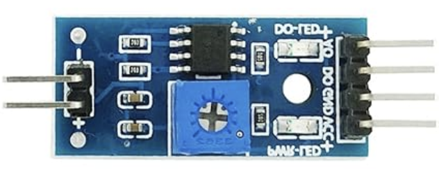
Pin Configuration and Descriptions
The FSR402 module typically has three pins for easy integration into circuits. Below is the pinout description:
| Pin Number | Pin Name | Description |
|---|---|---|
| 1 | Input (VIN) | Connect to the unregulated input voltage source. |
| 2 | Ground (GND) | Connect to the circuit ground. |
| 3 | Output (VOUT) | Provides the regulated output voltage. |
Usage Instructions
How to Use the Component in a Circuit
Connect the Input Voltage (VIN):
Attach the unregulated voltage source (6V to 24V) to theVINpin. Ensure the input voltage is within the specified range to avoid damage to the module.Connect the Ground (GND):
Connect theGNDpin to the ground of your circuit. This establishes a common reference point for the module and the circuit.Connect the Output Voltage (VOUT):
Use theVOUTpin to power your load or circuit. The output voltage will be either 3.3V or 5V, depending on the module's configuration.Select the Output Voltage (if applicable):
Some versions of the FSR402 module include a jumper or switch to select between 3.3V and 5V output. Refer to the specific module's datasheet for details.Add Decoupling Capacitors:
For optimal performance, place a capacitor (e.g., 10µF electrolytic and 0.1µF ceramic) betweenVOUTandGNDto reduce noise and improve stability.
Important Considerations and Best Practices
Heat Dissipation:
The FSR402 module may generate heat during operation, especially at high input voltages or currents. Use a heatsink or ensure proper ventilation to prevent overheating.Input Voltage Margin:
Ensure the input voltage is at least 1.1V higher than the desired output voltage to maintain proper regulation (dropout voltage).Load Current:
Do not exceed the maximum output current of 1.5A to avoid damaging the module.Polarity Protection:
Double-check the polarity of the input voltage to prevent reverse voltage damage.
Example: Using the FSR402 with an Arduino UNO
Below is an example of how to use the FSR402 module to power an Arduino UNO with a 12V input source:
Circuit Connections
- Connect the 12V input source to the
VINpin of the FSR402. - Connect the
GNDpin of the FSR402 to the ground of the Arduino UNO. - Connect the
VOUTpin of the FSR402 to theVINpin of the Arduino UNO.
Sample Code
// Example code to read an analog sensor powered by the FSR402 module
// Ensure the FSR402 is providing a stable 5V output to the Arduino UNO

const int sensorPin = A0; // Analog pin connected to the sensor
int sensorValue = 0;      // Variable to store the sensor reading

void setup() {
  Serial.begin(9600); // Initialize serial communication
}

void loop() {
  sensorValue = analogRead(sensorPin); // Read the sensor value
  Serial.print("Sensor Value: ");
  Serial.println(sensorValue); // Print the sensor value to the Serial Monitor
  delay(500); // Wait for 500ms before the next reading
}
Troubleshooting and FAQs
Common Issues and Solutions
No Output Voltage:
- Cause: Input voltage is below the minimum required level.
- Solution: Ensure the input voltage is within the 6V to 24V range.
Overheating:
- Cause: Excessive current draw or insufficient heat dissipation.
- Solution: Reduce the load current or attach a heatsink to the module.
Output Voltage Fluctuations:
- Cause: Insufficient decoupling capacitors or unstable input voltage.
- Solution: Add a 10µF electrolytic and 0.1µF ceramic capacitor between
VOUTandGND.
Incorrect Output Voltage:
- Cause: Output voltage selector is set incorrectly (if applicable).
- Solution: Verify and adjust the jumper or switch to select the desired output voltage.
FAQs
Q: Can I use the FSR402 module to power a 3.3V microcontroller?
A: Yes, the FSR402 can provide a stable 3.3V output. Ensure the module is configured for 3.3V operation.
Q: What happens if I exceed the maximum input voltage?
A: Exceeding 24V may damage the module. Always ensure the input voltage is within the specified range.
Q: Can I use the FSR402 with a battery-powered circuit?
A: Yes, the FSR402 is suitable for battery-powered circuits, provided the battery voltage is within the input range.
Q: Is the FSR402 suitable for high-frequency applications?
A: While the FSR402 provides low noise, it is not optimized for high-frequency switching applications. Consider using a switching regulator for such cases.