How to Use opencr: Examples, Pinouts, and Specs
Introduction
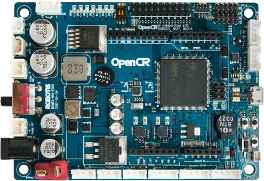
OpenCR (Open-source Control for Robotics) is a versatile open-source robotics controller designed for a wide range of robotic applications. It is equipped with a powerful microcontroller, multiple input/output (I/O) ports, and support for various communication protocols. OpenCR is ideal for controlling motors, sensors, and other peripherals in robotics projects. Its compatibility with popular development platforms like ROS (Robot Operating System) and Arduino makes it a preferred choice for both hobbyists and professionals.
Explore Projects Built with opencr

Explore Projects Built with opencr
Common Applications and Use Cases
- Autonomous robots and mobile platforms
- Humanoid robots and robotic arms
- Sensor integration and data acquisition
- Motor control for wheeled or legged robots
- Educational robotics projects
- ROS-based robotic systems
Technical Specifications
Key Technical Details
- Microcontroller: STM32F746ZGT6 (ARM Cortex-M7, 32-bit, 216 MHz)
- Operating Voltage: 3.3V (logic level)
- Input Voltage Range: 6.5V to 16V (via power input)
- Communication Protocols: UART, I2C, SPI, CAN, USB 2.0
- Motor Control: Supports Dynamixel servos and DC motors
- GPIO Pins: 40+ pins for digital and analog I/O
- PWM Channels: 16 channels
- Flash Memory: 1 MB
- RAM: 320 KB
- Connectivity: USB Micro-B, UART, CAN, and Bluetooth (optional module)
- Dimensions: 100 mm x 75 mm
- Weight: 70 g
Pin Configuration and Descriptions
The OpenCR board features multiple connectors and pins for various functionalities. Below is a summary of the key pin configurations:
Power Input and Control
| Pin/Port Name | Description |
|---|---|
| VIN | Main power input (6.5V to 16V) |
| VCC | 3.3V regulated output |
| GND | Ground |
| POWER_SW | Power switch control |
Communication Interfaces
| Pin/Port Name | Description |
|---|---|
| UART1 | Serial communication (TX, RX) |
| I2C1 | I2C communication (SCL, SDA) |
| SPI1 | SPI communication (MOSI, MISO, SCK) |
| CAN | CAN bus communication |
| USB | USB Micro-B for programming/debugging |
GPIO and PWM
| Pin/Port Name | Description |
|---|---|
| GPIO1-40 | General-purpose digital I/O pins |
| PWM1-16 | PWM output channels |
| ADC1-8 | Analog input channels |
Motor and Sensor Ports
| Pin/Port Name | Description |
|---|---|
| DXL_PWR | Power for Dynamixel servos |
| DXL_TX/RX | Communication for Dynamixel servos |
| SENSOR1-4 | Dedicated sensor ports |
Usage Instructions
How to Use OpenCR in a Circuit
- Powering the Board: Connect a power source (6.5V to 16V) to the VIN pin or use a USB connection for low-power applications.
- Connecting Motors and Sensors: Use the dedicated Dynamixel ports for servos and the SENSOR ports for external sensors.
- Programming the Board:
- Install the Arduino IDE and add the OpenCR board package.
- Connect the board to your computer via the USB Micro-B port.
- Select "OpenCR" as the board type in the Arduino IDE.
- Write and upload your code to the board.
Important Considerations and Best Practices
- Ensure the input voltage does not exceed the specified range to avoid damage.
- Use proper grounding when connecting external devices to prevent noise or interference.
- When using Dynamixel servos, ensure the DXL_PWR port is supplied with the appropriate voltage.
- For ROS integration, install the required ROS packages and configure the OpenCR firmware accordingly.
Example Code for Arduino UNO Integration
Below is an example of controlling a Dynamixel servo using OpenCR and Arduino IDE:
#include <DynamixelSDK.h> // Include the Dynamixel SDK library

#define DXL_ID 1           // ID of the Dynamixel servo
#define BAUDRATE 57600     // Communication baud rate
#define DEVICENAME ""      // Leave empty for OpenCR's default port

DynamixelSDK dxl;          // Create a DynamixelSDK object

void setup() {
  Serial.begin(115200);    // Initialize serial communication
  dxl.begin(BAUDRATE);     // Initialize Dynamixel communication

  // Set the operating mode to position control
  dxl.setOperatingMode(DXL_ID, POSITION_CONTROL_MODE);

  // Enable the Dynamixel servo
  dxl.torqueEnable(DXL_ID);
}

void loop() {
  // Move the servo to position 512 (midpoint)
  dxl.setGoalPosition(DXL_ID, 512);
  delay(1000); // Wait for 1 second

  // Move the servo to position 1023 (maximum)
  dxl.setGoalPosition(DXL_ID, 1023);
  delay(1000); // Wait for 1 second
}
Troubleshooting and FAQs
Common Issues and Solutions
Board Not Detected by Computer:
- Ensure the USB cable is properly connected.
- Verify that the correct drivers are installed for OpenCR.
- Check if the board is powered on.
Dynamixel Servos Not Responding:
- Confirm that the DXL_PWR port is receiving the correct voltage.
- Verify the servo ID and baud rate in the code.
- Check the wiring and connections.
Program Upload Fails:
- Ensure the correct board type and port are selected in the Arduino IDE.
- Press the reset button on the OpenCR board and try uploading again.
Unexpected Behavior in ROS:
- Verify that the ROS packages are correctly installed.
- Check the firmware version and update if necessary.
- Ensure proper configuration of the ROS nodes and topics.
FAQs
Can OpenCR be used without ROS? Yes, OpenCR can be programmed using the Arduino IDE for standalone applications.
What types of motors are supported? OpenCR supports Dynamixel servos and DC motors.
Is OpenCR compatible with Raspberry Pi? Yes, OpenCR can communicate with Raspberry Pi via UART, USB, or other supported protocols.
How do I update the firmware? Use the OpenCR Bootloader tool or the Arduino IDE to upload the latest firmware.
By following this documentation, you can effectively utilize OpenCR for your robotics projects.