
How to Use Adafruit I2C QT Rotary Encoder: Examples, Pinouts, and Specs
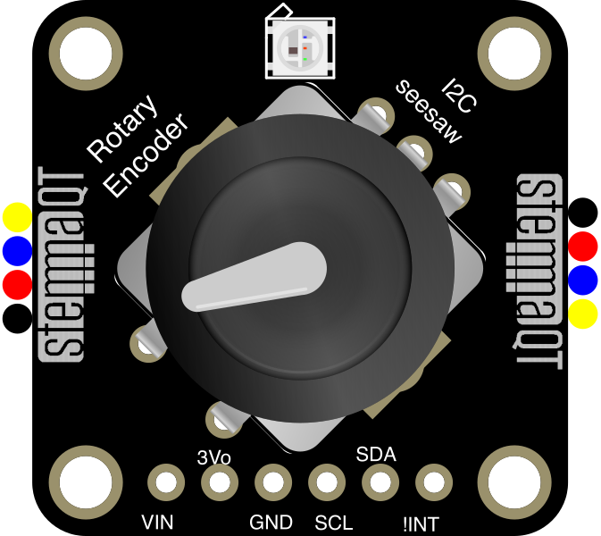
 Design with Adafruit I2C QT Rotary Encoder in Cirkit Designer
Introduction
The Adafruit I2C QT Rotary Encoder (Part ID: 4991) is a versatile and precise rotary encoder module that communicates via the I2C protocol. It features a built-in push button, making it an excellent choice for user interface applications such as menu navigation, volume control, and parameter adjustments. Its compact design and compatibility with microcontrollers, including Arduino, make it easy to integrate into a wide range of projects.
Explore Projects Built with Adafruit I2C QT Rotary Encoder
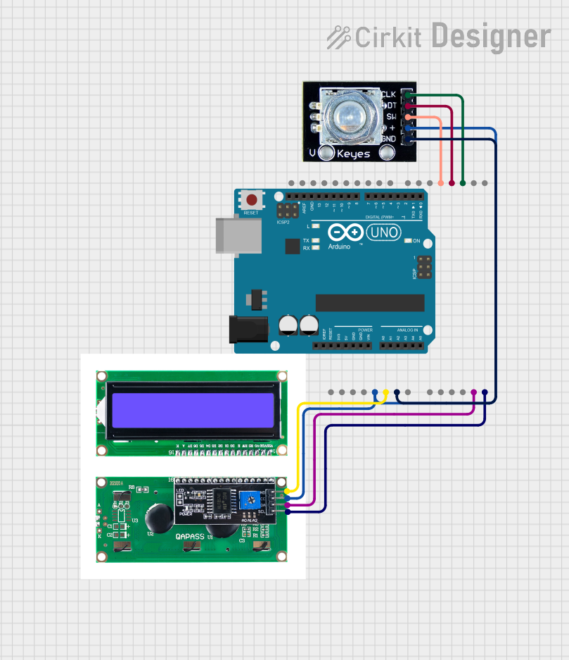 Open Project in Cirkit Designer
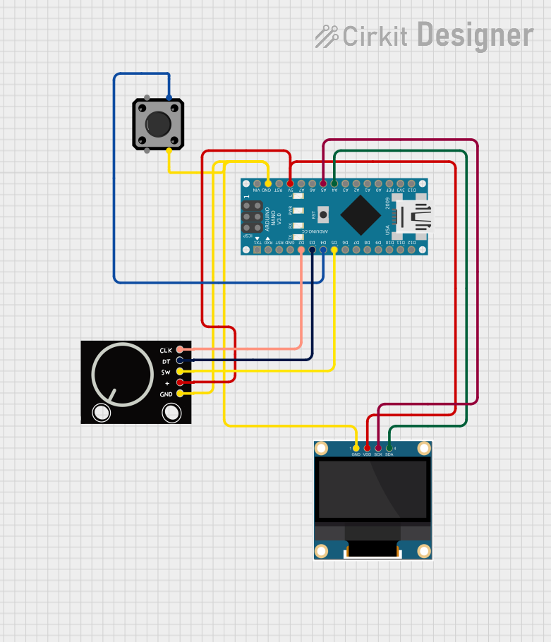 Open Project in Cirkit Designer
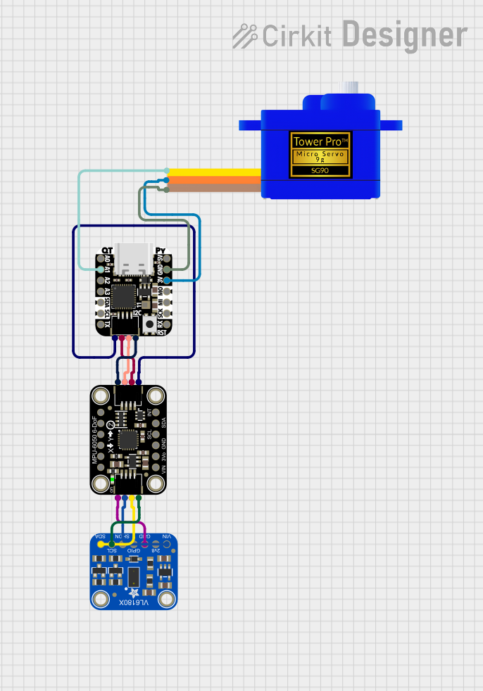 Open Project in Cirkit Designer
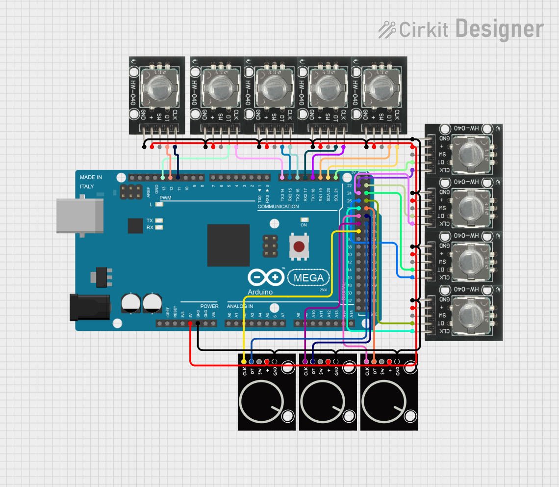 Open Project in Cirkit Designer
Explore Projects Built with Adafruit I2C QT Rotary Encoder
Open Project in Cirkit DesignerOpen Project in Cirkit DesignerOpen Project in Cirkit DesignerOpen Project in Cirkit DesignerCommon Applications
- User interface controls (e.g., menu navigation, volume adjustment)
- Robotics (e.g., position feedback)
- Industrial control systems
- DIY electronics projects
- Gaming controllers
Technical Specifications
The Adafruit I2C QT Rotary Encoder is designed for ease of use and reliable performance. Below are its key technical details:
Key Specifications
| Parameter | Value |
|---|---|
| Communication Protocol | I2C |
| Operating Voltage | 3.3V to 5V |
| Current Consumption | ~5mA |
| Encoder Resolution | 24 pulses per revolution |
| Push Button | Integrated |
| I2C Address (Default) | 0x36 |
| Dimensions | 20mm x 17mm x 4mm |
| Mounting Style | STEMMA QT / Qwiic connectors |
Pin Configuration
The Adafruit I2C QT Rotary Encoder features a STEMMA QT connector for easy I2C interfacing. Below is the pinout:
| Pin Name | Description |
|---|---|
| VIN | Power input (3.3V to 5V) |
| GND | Ground |
| SCL | I2C clock line |
| SDA | I2C data line |
Usage Instructions
Connecting the Encoder
- Power Supply: Connect the VIN pin to a 3.3V or 5V power source and the GND pin to ground.
- I2C Connection: Connect the SCL and SDA pins to the corresponding I2C pins on your microcontroller. For an Arduino UNO:
- SCL connects to A5.
- SDA connects to A4.
- Optional: Use the STEMMA QT connectors for a solder-free connection.
Using the Encoder with Arduino
To use the Adafruit I2C QT Rotary Encoder with an Arduino, you will need the Adafruit Seesaw library. Follow these steps:
- Install the Adafruit Seesaw library via the Arduino Library Manager.
- Connect the encoder to the Arduino as described above.
- Upload the following example code to read the encoder position and button state:
#include <Wire.h>
#include "Adafruit_seesaw.h"

// Create a seesaw object for the rotary encoder
Adafruit_seesaw ss;

void setup() {
  Serial.begin(115200);
  while (!Serial) delay(10); // Wait for Serial Monitor to open

  // Initialize the seesaw encoder
  if (!ss.begin(0x36)) { // Default I2C address is 0x36
    Serial.println("Failed to find seesaw device!");
    while (1) delay(10);
  }
  Serial.println("Seesaw device found!");

  // Enable the encoder and button
  ss.encoderEnable();
}

void loop() {
  // Read the encoder position
  int32_t position = ss.encoderRead();
  Serial.print("Encoder Position: ");
  Serial.println(position);

  // Read the button state
  uint8_t button = ss.digitalRead(24); // Button is on pin 24
  if (button == 0) {
    Serial.println("Button Pressed!");
  }

  delay(100); // Small delay for stability
}
Important Considerations
- I2C Address Conflicts: If multiple I2C devices are connected, ensure they have unique addresses. The encoder's default address is
0x36. - Debouncing: The built-in button may require software debouncing for reliable operation.
- Power Supply: Ensure the power supply voltage matches the encoder's operating range (3.3V to 5V).
Troubleshooting and FAQs
Common Issues
Encoder Not Detected on I2C Bus
- Solution: Verify the wiring and ensure the SCL and SDA lines are correctly connected. Use an I2C scanner sketch to confirm the encoder's address.
Incorrect Position Readings
- Solution: Check for loose connections or electrical noise. Ensure the encoder is securely mounted.
Button Not Responding
- Solution: Verify the button pin (24) is being read correctly in the code. Check for physical damage to the button.
Multiple Devices on I2C Bus Not Working
- Solution: Ensure all devices have unique I2C addresses. If necessary, change the encoder's address using the Adafruit Seesaw library.
FAQs
Q: Can I use this encoder with a Raspberry Pi?
A: Yes, the encoder is compatible with Raspberry Pi. Use the I2C pins on the Raspberry Pi and install the Adafruit Seesaw Python library.
Q: How do I change the I2C address?
A: Use the Adafruit Seesaw library to set a new address. Refer to the library documentation for details.
Q: Is the encoder suitable for high-speed applications?
A: The encoder is designed for user interface applications and may not be suitable for high-speed rotary motion.
Q: Can I daisy-chain multiple encoders?
A: Yes, using the STEMMA QT connectors, you can daisy-chain multiple devices, provided each has a unique I2C address.
This concludes the documentation for the Adafruit I2C QT Rotary Encoder. For further assistance, refer to the Adafruit product page or community forums.