How to Use VCC 5V: Examples, Pinouts, and Specs

 Design with VCC 5V in Cirkit Designer
Introduction
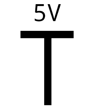
The VCC 5V is a power supply voltage source that provides a constant 5 volts. It is one of the most commonly used voltage levels in electronic circuits, powering a wide range of components such as microcontrollers, sensors, LEDs, and other low-power devices. Its reliability and compatibility make it a standard choice for many applications in embedded systems, robotics, and prototyping.
Explore Projects Built with VCC 5V

 Open Project in Cirkit Designer
 Open Project in Cirkit Designer
 Open Project in Cirkit Designer
 Open Project in Cirkit Designer
Explore Projects Built with VCC 5V

 Open Project in Cirkit Designer
 Open Project in Cirkit Designer
 Open Project in Cirkit Designer
 Open Project in Cirkit Designer
Common Applications and Use Cases
- Powering microcontrollers like Arduino, Raspberry Pi, and ESP32.
- Supplying voltage to sensors (e.g., temperature, humidity, and motion sensors).
- Driving low-power actuators such as small DC motors and servos.
- Providing power to communication modules like Bluetooth, Wi-Fi, and GSM modules.
- General-purpose use in breadboard prototyping and circuit testing.
Technical Specifications
The VCC 5V power source is typically derived from a regulated power supply, USB port, or a voltage regulator IC. Below are the key technical details:
Key Technical Details
- Voltage Output: 5V DC (Direct Current)
- Current Rating: Varies depending on the source (e.g., USB: 500mA to 2A, voltage regulator: up to 1.5A)
- Ripple Voltage: Typically less than 50mV (depends on the regulator and filtering)
- Polarity: Positive voltage output with respect to ground (GND)
Pin Configuration and Descriptions
The VCC 5V source is often represented as a pin or terminal in circuits. Below is a typical configuration:
| Pin Name | Description |
|---|---|
| VCC (5V) | Positive 5V DC output |
| GND | Ground (0V reference for the circuit) |
Usage Instructions
How to Use the VCC 5V in a Circuit
- Connect the VCC Pin: Attach the VCC 5V pin to the power input of your component or circuit. Ensure the component is designed to operate at 5V.
- Connect the GND Pin: Connect the ground (GND) pin of the VCC source to the ground of your circuit. This establishes a common reference point for the voltage.
- Verify Current Requirements: Ensure the VCC 5V source can supply sufficient current for all connected components. Exceeding the current rating may cause voltage drops or damage the power source.
- Add Decoupling Capacitors: Place a 0.1µF ceramic capacitor and a 10µF electrolytic capacitor near the power input of your circuit to filter noise and stabilize the voltage.
Important Considerations and Best Practices
- Polarity Check: Always verify the polarity of the VCC and GND connections to avoid damaging components.
- Voltage Tolerance: Ensure the connected components can tolerate slight variations in the 5V supply (e.g., ±5%).
- Heat Dissipation: If using a voltage regulator to generate 5V, ensure proper heat dissipation with a heatsink if the current draw is high.
- Avoid Overloading: Do not exceed the current rating of the VCC 5V source to prevent overheating or failure.
Example: Using VCC 5V with an Arduino UNO
The Arduino UNO has a 5V pin that can be used as a VCC source. Below is an example of powering an LED with a 5V supply:
// Example: Powering an LED with VCC 5V on Arduino UNO

// Define the pin connected to the LED
const int ledPin = 13; // Pin 13 is connected to the onboard LED

void setup() {
  pinMode(ledPin, OUTPUT); // Set the LED pin as an output
}

void loop() {
  digitalWrite(ledPin, HIGH); // Turn the LED on
  delay(1000);                // Wait for 1 second
  digitalWrite(ledPin, LOW);  // Turn the LED off
  delay(1000);                // Wait for 1 second
}
Troubleshooting and FAQs
Common Issues and Solutions
No Output Voltage:
- Cause: The power source is not connected or turned on.
- Solution: Verify the power source is properly connected and powered.
Voltage Drops Below 5V:
- Cause: The current draw exceeds the source's capacity.
- Solution: Use a higher current-rated power source or reduce the load.
Components Not Working:
- Cause: Incorrect polarity or loose connections.
- Solution: Double-check the VCC and GND connections for proper polarity and secure connections.
Excessive Heat from Voltage Regulator:
- Cause: High current draw or insufficient heat dissipation.
- Solution: Add a heatsink to the regulator or reduce the load.
FAQs
Q: Can I use a USB port as a VCC 5V source?
A: Yes, USB ports typically provide 5V, but the current capacity depends on the port type (e.g., USB 2.0: 500mA, USB 3.0: 900mA). Ensure your circuit does not exceed the port's current rating.
Q: What happens if I connect a 3.3V device to VCC 5V?
A: Connecting a 3.3V device to a 5V supply may damage the device. Use a voltage regulator or level shifter to step down the voltage.
Q: How do I protect my circuit from voltage spikes?
A: Use a TVS diode or a capacitor across the VCC and GND lines to suppress voltage spikes and noise.
Q: Can I use VCC 5V to power multiple components?
A: Yes, as long as the total current draw of all components does not exceed the current rating of the VCC 5V source.