
How to Use LilyPad XBee: Examples, Pinouts, and Specs
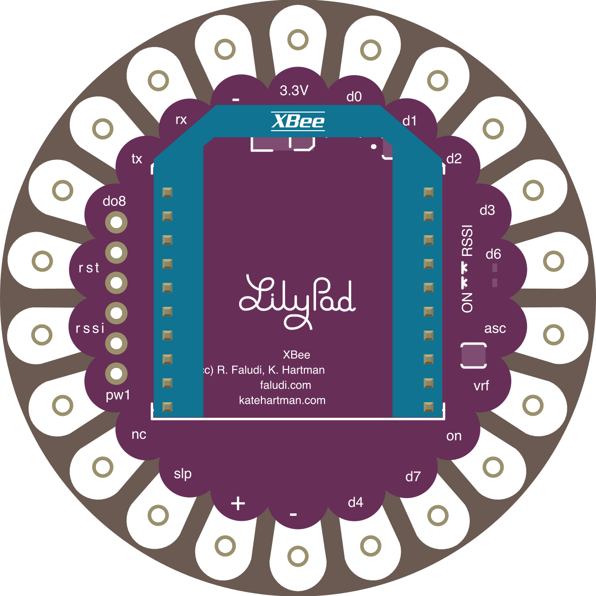
 Design with LilyPad XBee in Cirkit Designer
Introduction
The LilyPad XBee (Manufacturer Part ID: DEV-08937) is a wireless communication module designed by SparkFun Electronics. It is specifically tailored for use with the LilyPad Arduino platform, enabling seamless integration of XBee wireless technology into wearable and textile projects. This module allows for reliable wireless communication between devices, making it ideal for applications such as remote sensing, data logging, and interactive wearable designs.
Explore Projects Built with LilyPad XBee
 Open Project in Cirkit Designer
 Open Project in Cirkit Designer
 Open Project in Cirkit Designer
 Open Project in Cirkit Designer
Explore Projects Built with LilyPad XBee
Open Project in Cirkit DesignerOpen Project in Cirkit DesignerOpen Project in Cirkit DesignerOpen Project in Cirkit DesignerCommon Applications and Use Cases
- Wearable Electronics: Enables wireless communication in e-textile projects.
- Remote Sensing: Transmit sensor data wirelessly to a central hub.
- Interactive Installations: Create responsive systems that communicate wirelessly.
- IoT Prototyping: Build Internet of Things (IoT) devices with wireless connectivity.
- Educational Projects: Learn about wireless communication in a hands-on way.
Technical Specifications
The LilyPad XBee is designed to work seamlessly with XBee modules and the LilyPad Arduino ecosystem. Below are its key technical details:
Key Technical Details
- Input Voltage: 3.3V (regulated)
- Communication Protocol: UART (Serial)
- Compatibility: XBee Series 1 and Series 2 modules
- Dimensions: 50mm x 34mm
- Weight: 4.5g
- Mounting: Sewable pads for textile integration
- Operating Temperature: -40°C to 85°C (dependent on the XBee module used)
Pin Configuration and Descriptions
The LilyPad XBee features sewable pads for easy integration into fabric-based projects. Below is the pin configuration:
| Pin Name | Description |
|---|---|
| VCC | Power input (3.3V regulated). Supplies power to the XBee module. |
| GND | Ground connection. |
| TX | Transmit pin. Sends serial data from the XBee module to the microcontroller. |
| RX | Receive pin. Receives serial data from the microcontroller to the XBee module. |
| DOUT | Digital output from the XBee module. |
| DIN | Digital input to the XBee module. |
Usage Instructions
The LilyPad XBee is straightforward to use in wearable and textile projects. Below are the steps and best practices for integrating it into your designs.
How to Use the LilyPad XBee in a Circuit
- Power the Module: Connect the VCC pad to a 3.3V power source and the GND pad to ground.
- Connect to a Microcontroller:
- Connect the TX pad of the LilyPad XBee to the RX pin of your microcontroller.
- Connect the RX pad of the LilyPad XBee to the TX pin of your microcontroller.
- Attach to Fabric: Use conductive thread to sew the module onto fabric. Ensure secure connections to the sewable pads.
- Configure the XBee Module: Use an XBee USB adapter or an FTDI breakout board to configure the XBee module using software like XCTU.
- Write Code: Program your microcontroller to send and receive data via the XBee module.
Important Considerations and Best Practices
- Voltage Regulation: Ensure the module is powered with a regulated 3.3V supply. Exceeding this voltage may damage the XBee module.
- Conductive Thread: Use high-quality conductive thread for reliable connections. Avoid crossing threads to prevent short circuits.
- Antenna Placement: Ensure the XBee module's antenna is not obstructed by conductive materials for optimal wireless performance.
- XBee Configuration: Configure the XBee module's PAN ID, baud rate, and other settings to match your application requirements.
Example Code for Arduino UNO
Below is an example of how to use the LilyPad XBee with an Arduino UNO to send and receive data wirelessly:
#include <SoftwareSerial.h>

// Define RX and TX pins for the XBee module
SoftwareSerial XBee(2, 3); // RX = Pin 2, TX = Pin 3

void setup() {
  // Initialize serial communication with the XBee module
  XBee.begin(9600); // Set baud rate to match XBee configuration
  Serial.begin(9600); // For debugging via Serial Monitor

  Serial.println("LilyPad XBee Communication Initialized");
}

void loop() {
  // Send data to the XBee module
  XBee.println("Hello from Arduino!");

  // Check if data is available from the XBee module
  if (XBee.available()) {
    String receivedData = XBee.readString(); // Read incoming data
    Serial.print("Received: ");
    Serial.println(receivedData); // Print received data to Serial Monitor
  }

  delay(1000); // Wait 1 second before sending the next message
}
Notes on the Code
- Ensure the XBee module is configured to communicate at the same baud rate as specified in the code (9600 in this case).
- Use pins 2 and 3 on the Arduino UNO for software serial communication with the LilyPad XBee.
Troubleshooting and FAQs
Common Issues and Solutions
No Communication Between Devices
- Cause: Mismatched baud rates between the XBee module and the microcontroller.
- Solution: Verify and configure the XBee module's baud rate using XCTU software.
Intermittent Wireless Connection
- Cause: Poor antenna placement or interference from conductive materials.
- Solution: Ensure the XBee module's antenna is unobstructed and positioned away from conductive materials.
Module Not Powering On
- Cause: Incorrect voltage supply.
- Solution: Ensure the module is powered with a regulated 3.3V supply.
Short Circuits in Textile Projects
- Cause: Conductive threads crossing or fraying.
- Solution: Use insulating materials or fabric glue to secure threads and prevent shorts.
FAQs
Q: Can I use the LilyPad XBee with a 5V microcontroller?
A: Yes, but you must use a level shifter or voltage divider to step down the 5V signals to 3.3V for the XBee module.
Q: How far can the XBee module communicate?
A: The range depends on the specific XBee module used. For example, XBee Series 1 modules typically have a range of up to 100 meters in open air.
Q: Can I use the LilyPad XBee without a microcontroller?
A: Yes, the XBee module can operate in standalone mode for simple communication tasks, but a microcontroller is required for more complex operations.
Q: How do I sew the module onto fabric?
A: Use conductive thread to sew through the sewable pads. Ensure tight and secure stitches for reliable connections.
By following this documentation, you can effectively integrate the LilyPad XBee into your wearable and textile projects, enabling robust wireless communication.