Cirkit Designer
Your all-in-one circuit design IDE
Home /
Component Documentation
How to Use CONTROLLER: Examples, Pinouts, and Specs
Introduction
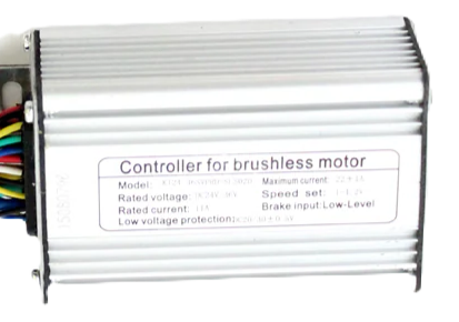
A controller is a device or set of devices that manages, commands, directs, or regulates the behavior of other devices or systems. In electronics, it often refers to a microcontroller or a programmable logic controller (PLC) used to control various functions in a circuit. Controllers are integral to modern electronics, enabling automation, precise control, and complex functionality in a wide range of applications.
Explore Projects Built with CONTROLLER
Arduino Mega 2560-Controlled Servo System with Bluetooth and Sensor Interface

This is a microcontroller-based control system featuring an Arduino Mega 2560, designed to receive inputs from a rotary potentiometer, push switches, and an IR sensor, and to drive multiple servos and an LCD display. It includes an HC-05 Bluetooth module for wireless communication, allowing for remote interfacing and control.
Arduino-Controlled Motor System with Bluetooth Connectivity
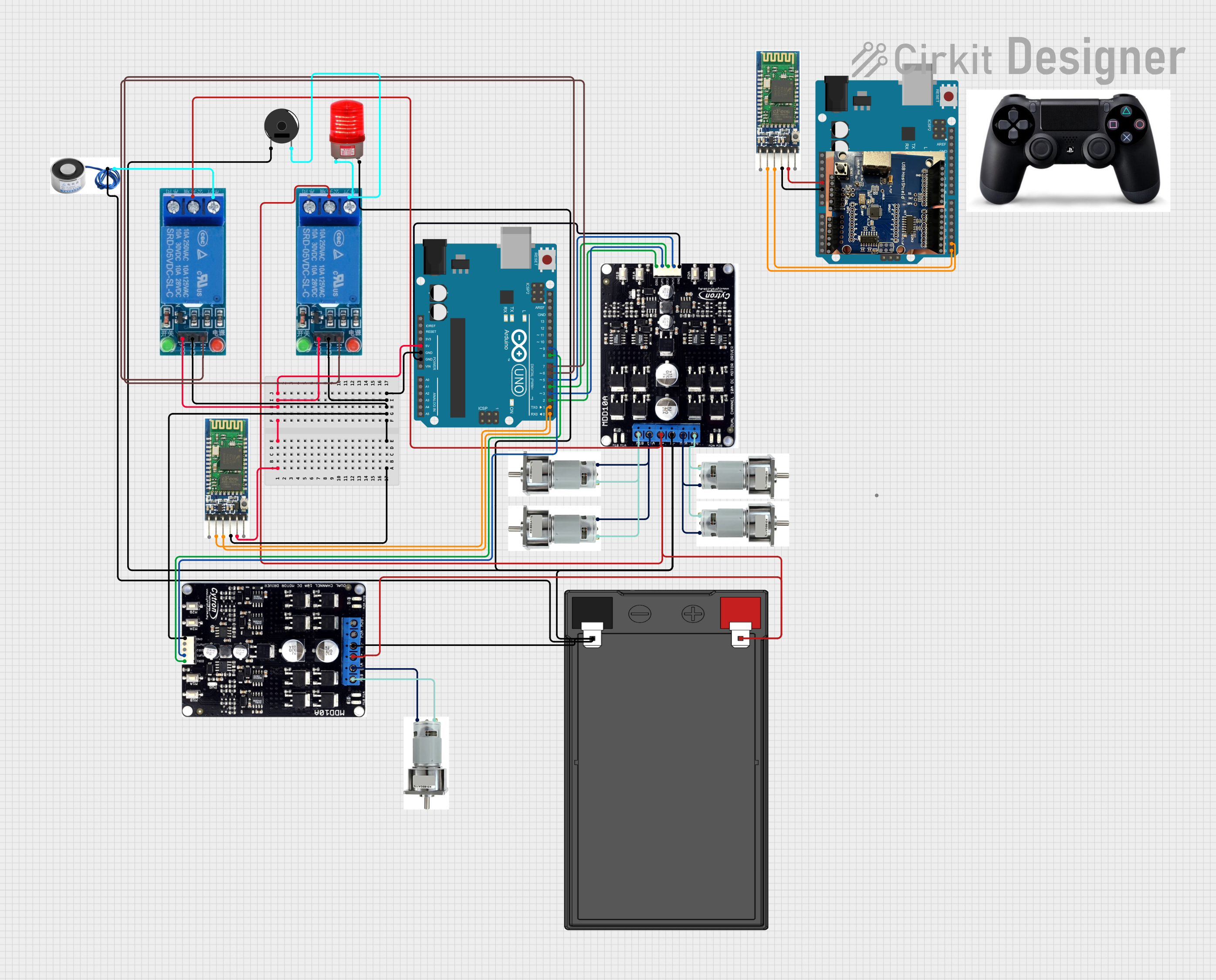
This is a motor control system with wireless communication capabilities, designed to operate multiple motors via Cytron motor drivers, controlled by Arduino UNOs. It includes relays for activating a light and buzzer, and uses Bluetooth for remote operation. The system's software is in the initial stages of development.
ESP8266 Controlled Robotics Platform with GPS, IR, and GSM Features
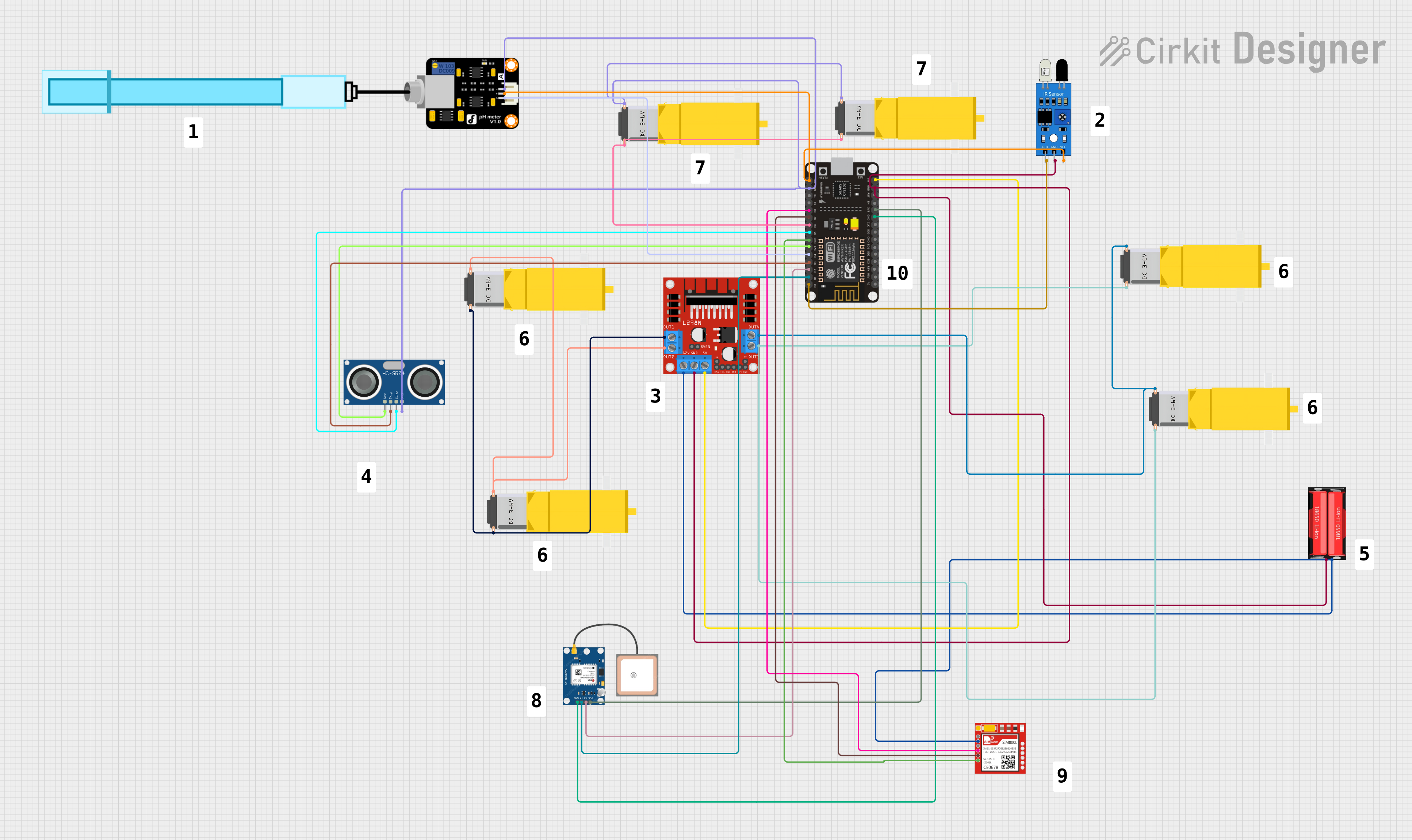
This is a microcontroller-based control system designed for a mobile robotic platform with environmental sensing, location tracking, and GSM communication capabilities. It includes motor control for actuation, various sensors for data acquisition, and a battery for power supply.
Arduino UNO-Based Coin-Operated Communication System with LCD Display and Servo Control
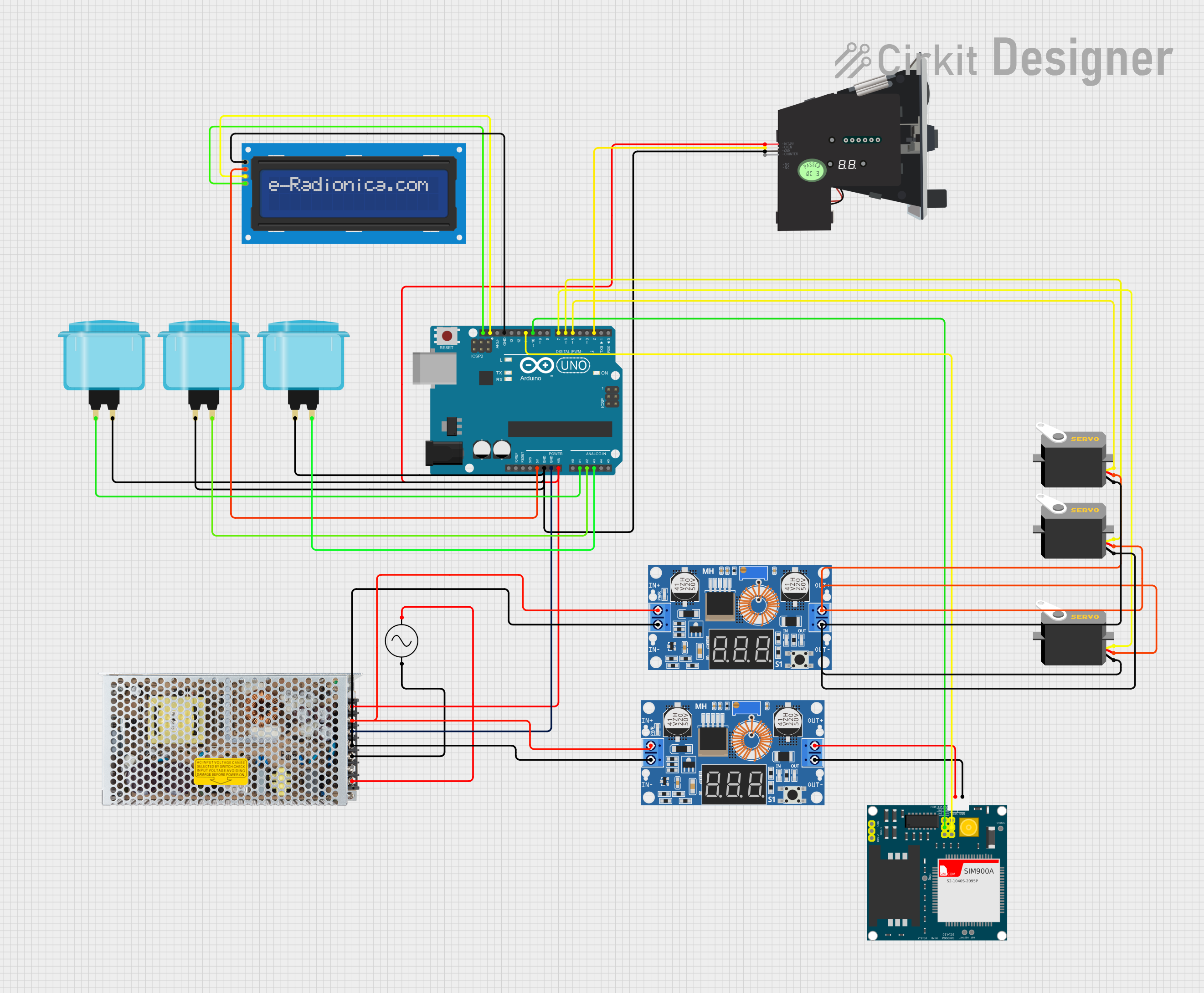
This is a microcontroller-based control system for a vending or arcade application, featuring an Arduino UNO that manages user inputs through arcade buttons, drives servos, displays information on an LCD, and communicates over GSM with the SIM900A module. Power regulation is achieved through a switching power supply and DC-DC buck converters.
Explore Projects Built with CONTROLLER
Arduino Mega 2560-Controlled Servo System with Bluetooth and Sensor Interface
This is a microcontroller-based control system featuring an Arduino Mega 2560, designed to receive inputs from a rotary potentiometer, push switches, and an IR sensor, and to drive multiple servos and an LCD display. It includes an HC-05 Bluetooth module for wireless communication, allowing for remote interfacing and control.
Arduino-Controlled Motor System with Bluetooth Connectivity
This is a motor control system with wireless communication capabilities, designed to operate multiple motors via Cytron motor drivers, controlled by Arduino UNOs. It includes relays for activating a light and buzzer, and uses Bluetooth for remote operation. The system's software is in the initial stages of development.
ESP8266 Controlled Robotics Platform with GPS, IR, and GSM Features
This is a microcontroller-based control system designed for a mobile robotic platform with environmental sensing, location tracking, and GSM communication capabilities. It includes motor control for actuation, various sensors for data acquisition, and a battery for power supply.
Arduino UNO-Based Coin-Operated Communication System with LCD Display and Servo Control
This is a microcontroller-based control system for a vending or arcade application, featuring an Arduino UNO that manages user inputs through arcade buttons, drives servos, displays information on an LCD, and communicates over GSM with the SIM900A module. Power regulation is achieved through a switching power supply and DC-DC buck converters.
Common Applications and Use Cases
- Home Automation: Controllers are used to manage lighting, heating, and security systems.
- Industrial Automation: PLCs control machinery, assembly lines, and robotic systems.
- Consumer Electronics: Microcontrollers are found in devices like smartphones, gaming consoles, and appliances.
- Automotive Systems: Controllers manage engine functions, infotainment systems, and safety features.
- IoT Devices: Controllers enable connectivity and control in smart devices and sensors.
Technical Specifications
Key Technical Details
| Specification | Value |
|---|---|
| Manufacturer | C |
| Part ID | C |
| Operating Voltage | 3.3V - 5V |
| Operating Current | 10mA - 50mA |
| Power Rating | 0.5W |
| Clock Speed | 16MHz |
| Memory | 32KB Flash, 2KB SRAM, 1KB EEPROM |
| I/O Pins | 14 Digital, 6 Analog |
| Communication | UART, SPI, I2C |
| Operating Temperature | -40°C to 85°C |
Pin Configuration and Descriptions
| Pin Number | Pin Name | Description |
|---|---|---|
| 1 | VCC | Power Supply (3.3V - 5V) |
| 2 | GND | Ground |
| 3 | D0 | Digital I/O Pin 0 |
| 4 | D1 | Digital I/O Pin 1 |
| 5 | D2 | Digital I/O Pin 2 |
| 6 | D3 | Digital I/O Pin 3 |
| 7 | D4 | Digital I/O Pin 4 |
| 8 | D5 | Digital I/O Pin 5 |
| 9 | D6 | Digital I/O Pin 6 |
| 10 | D7 | Digital I/O Pin 7 |
| 11 | D8 | Digital I/O Pin 8 |
| 12 | D9 | Digital I/O Pin 9 |
| 13 | D10 | Digital I/O Pin 10 |
| 14 | D11 | Digital I/O Pin 11 |
| 15 | D12 | Digital I/O Pin 12 |
| 16 | D13 | Digital I/O Pin 13 |
| 17 | A0 | Analog Input Pin 0 |
| 18 | A1 | Analog Input Pin 1 |
| 19 | A2 | Analog Input Pin 2 |
| 20 | A3 | Analog Input Pin 3 |
| 21 | A4 | Analog Input Pin 4 |
| 22 | A5 | Analog Input Pin 5 |
| 23 | RX | UART Receive |
| 24 | TX | UART Transmit |
| 25 | SCL | I2C Clock |
| 26 | SDA | I2C Data |
| 27 | MOSI | SPI Master Out Slave In |
| 28 | MISO | SPI Master In Slave Out |
| 29 | SCK | SPI Clock |
| 30 | RESET | Reset |
Usage Instructions
How to Use the Component in a Circuit
- Power Supply: Connect the VCC pin to a 3.3V or 5V power supply and the GND pin to ground.
- Digital I/O: Use the digital pins (D0-D13) for digital input and output operations.
- Analog Input: Use the analog pins (A0-A5) to read analog signals.
- Communication: Utilize the UART, SPI, and I2C pins for serial communication with other devices.
Important Considerations and Best Practices
- Power Supply: Ensure the power supply voltage matches the operating voltage range (3.3V - 5V).
- Pin Protection: Use current-limiting resistors on I/O pins to prevent damage.
- Decoupling Capacitors: Place decoupling capacitors close to the power pins to filter noise.
- Reset Pin: Connect a pull-up resistor to the RESET pin to ensure proper startup.
Example: Connecting to an Arduino UNO
// Example code to blink an LED connected to pin D13

void setup() {
  pinMode(13, OUTPUT); // Set pin D13 as an output
}

void loop() {
  digitalWrite(13, HIGH); // Turn the LED on
  delay(1000);            // Wait for 1 second
  digitalWrite(13, LOW);  // Turn the LED off
  delay(1000);            // Wait for 1 second
}
Troubleshooting and FAQs
Common Issues Users Might Face
- No Power: Ensure the VCC and GND pins are properly connected.
- Incorrect Pin Configuration: Double-check the pin connections and configurations.
- Communication Errors: Verify the communication protocol settings (baud rate, etc.).
- Overheating: Check for excessive current draw and ensure proper heat dissipation.
Solutions and Tips for Troubleshooting
- Check Connections: Ensure all connections are secure and correct.
- Use a Multimeter: Measure voltage and current to diagnose power issues.
- Review Code: Double-check the code for errors and correct pin assignments.
- Consult Datasheets: Refer to the manufacturer's datasheet for detailed specifications and guidelines.
By following this documentation, users can effectively integrate and utilize the controller in various electronic projects, ensuring reliable and efficient performance.