Cirkit Designer
Your all-in-one circuit design IDE
Home /
Component Documentation
How to Use dfrobot gyro: Examples, Pinouts, and Specs
Introduction
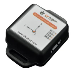
The DFRobot Gyroscope Sensor Module (Part ID: GYRO) is a versatile and reliable component designed to measure and maintain orientation and angular velocity. This sensor is widely used in various applications, including robotics, drones, gaming devices, and motion tracking systems. Its ability to provide precise rotational data makes it an essential component for projects requiring accurate motion sensing and control.
Explore Projects Built with dfrobot gyro
Arduino UNO Controlled Self-Balancing Robot with MPU-6050 and L298N Motor Driver
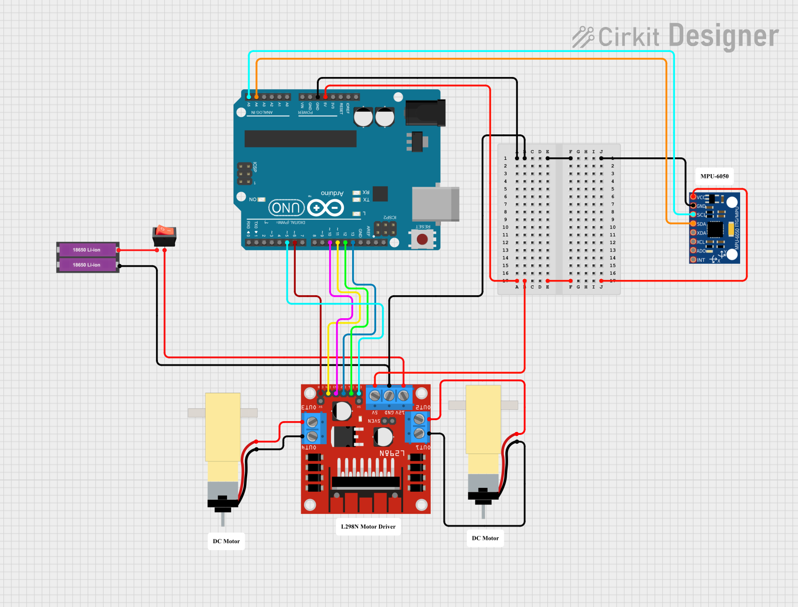
This circuit is designed to control a pair of DC motors using an Arduino UNO microcontroller and an L298N motor driver. The MPU-6050 gyroscope/accelerometer provides feedback for stabilizing the system, likely for a balancing robot or similar application. The Arduino's firmware is programmed to implement a PID controller, adjusting motor speeds based on the orientation data from the MPU-6050 to maintain a target position or balance.
Arduino Nano-Based Sign Language Translator with Flex Sensors and MPU-6050
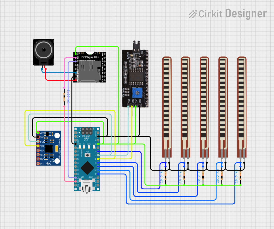
This circuit features an Arduino Nano interfaced with an MPU-6050 gyroscope/accelerometer and a DFPlayer Mini MP3 module connected to a loudspeaker for audio output. The Arduino reads values from five flex sensors and the MPU-6050 to monitor hand movements and orientation, likely for a sign language translation system. The DFPlayer Mini is controlled via serial communication to play audio files, possibly to output corresponding spoken words.
Arduino UNO Controlled Robotic Vehicle with MPU-6050 and Bluetooth Connectivity
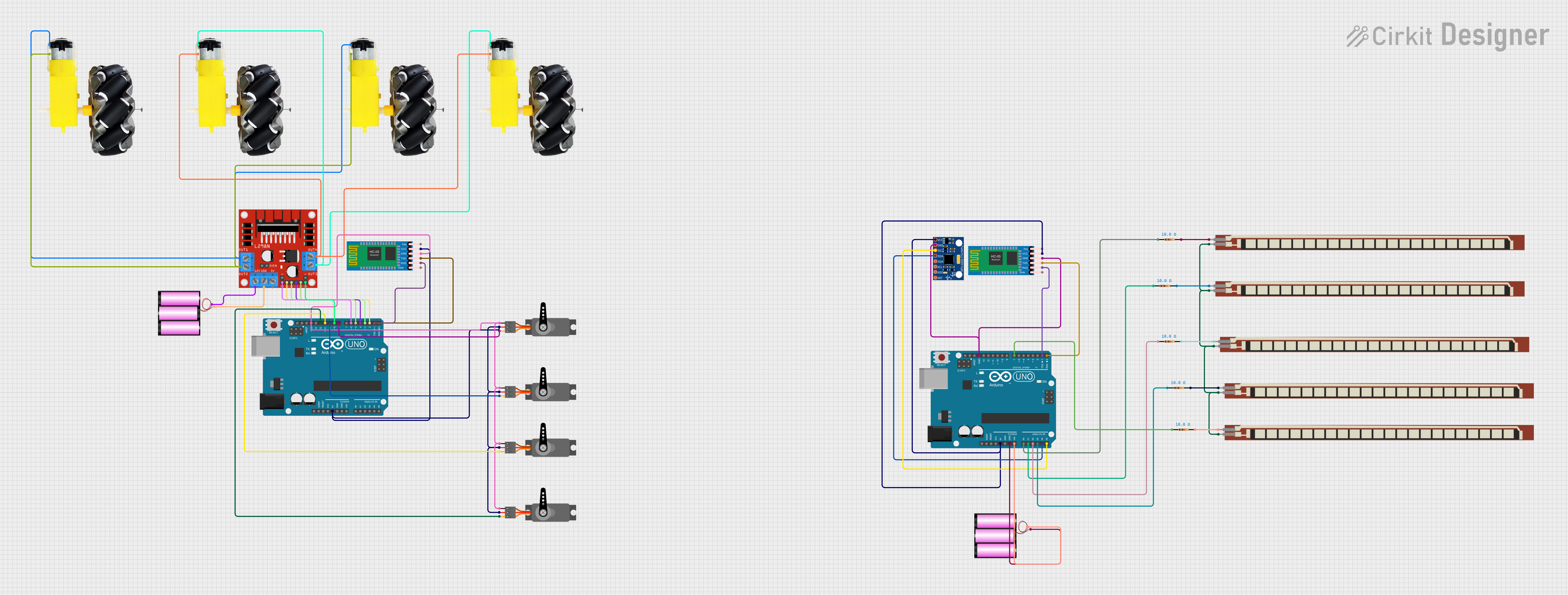
This is a robotic vehicle controlled by an Arduino UNO, equipped with an MPU-6050 for tilt-based movement, flex sensors for gesture control, and an L298N driver for motor control. It uses HC-05 Bluetooth modules for wireless communication, allowing remote operation and control of its movements and an attached robotic arm.
Arduino UNO-Based Robotic Arm with MPU6050 and Servo Motors
This circuit features an Arduino UNO microcontroller connected to an MPU6050 accelerometer and gyroscope sensor for motion detection, and four servos for actuation. The Arduino reads data from the MPU6050 via I2C communication and controls the servos through digital pins D7, D8, D10, and D11.
Explore Projects Built with dfrobot gyro
Arduino UNO Controlled Self-Balancing Robot with MPU-6050 and L298N Motor Driver
This circuit is designed to control a pair of DC motors using an Arduino UNO microcontroller and an L298N motor driver. The MPU-6050 gyroscope/accelerometer provides feedback for stabilizing the system, likely for a balancing robot or similar application. The Arduino's firmware is programmed to implement a PID controller, adjusting motor speeds based on the orientation data from the MPU-6050 to maintain a target position or balance.
Arduino Nano-Based Sign Language Translator with Flex Sensors and MPU-6050
This circuit features an Arduino Nano interfaced with an MPU-6050 gyroscope/accelerometer and a DFPlayer Mini MP3 module connected to a loudspeaker for audio output. The Arduino reads values from five flex sensors and the MPU-6050 to monitor hand movements and orientation, likely for a sign language translation system. The DFPlayer Mini is controlled via serial communication to play audio files, possibly to output corresponding spoken words.
Arduino UNO Controlled Robotic Vehicle with MPU-6050 and Bluetooth Connectivity
This is a robotic vehicle controlled by an Arduino UNO, equipped with an MPU-6050 for tilt-based movement, flex sensors for gesture control, and an L298N driver for motor control. It uses HC-05 Bluetooth modules for wireless communication, allowing remote operation and control of its movements and an attached robotic arm.
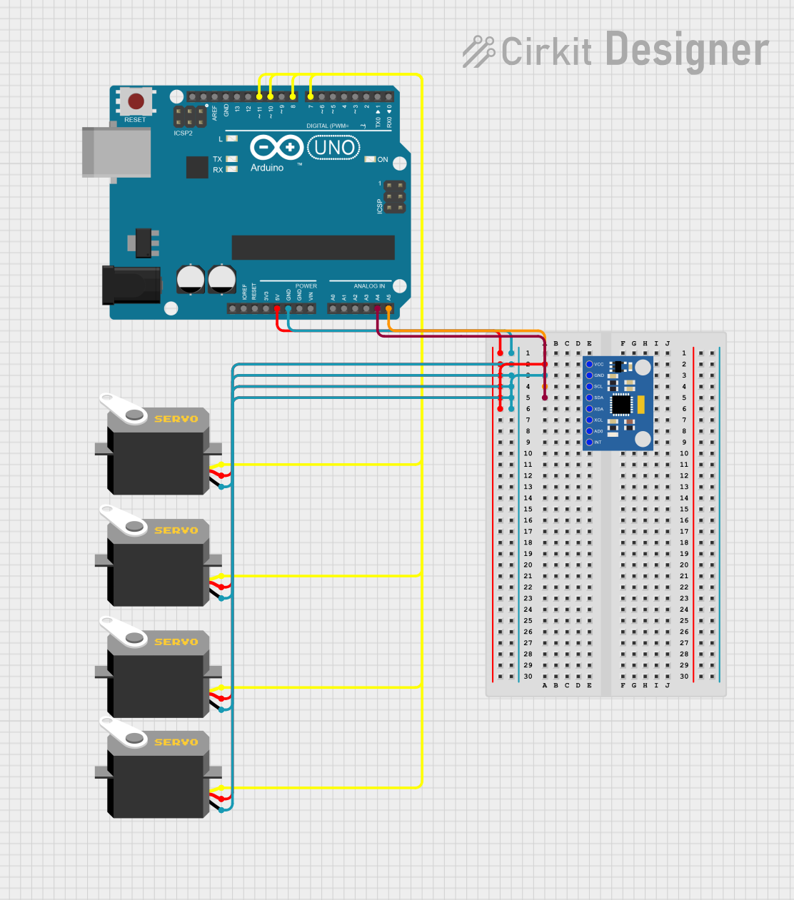
Arduino UNO-Based Robotic Arm with MPU6050 and Servo Motors
This circuit features an Arduino UNO microcontroller connected to an MPU6050 accelerometer and gyroscope sensor for motion detection, and four servos for actuation. The Arduino reads data from the MPU6050 via I2C communication and controls the servos through digital pins D7, D8, D10, and D11.
Technical Specifications
Key Technical Details
| Parameter | Value |
|---|---|
| Operating Voltage | 3.3V to 5V |
| Current Consumption | 3.6mA (typical) |
| Measurement Range | ±250, ±500, ±1000, ±2000 °/s |
| Communication Interface | I2C/SPI |
| Operating Temperature | -40°C to +85°C |
| Dimensions | 20mm x 20mm x 1.6mm |
Pin Configuration and Descriptions
| Pin | Name | Description |
|---|---|---|
| 1 | VCC | Power supply (3.3V to 5V) |
| 2 | GND | Ground |
| 3 | SCL | I2C Clock Line |
| 4 | SDA | I2C Data Line |
| 5 | CS | Chip Select (used for SPI communication) |
| 6 | INT | Interrupt Pin (optional, for motion detection) |
Usage Instructions
How to Use the Component in a Circuit
- Power Supply: Connect the VCC pin to a 3.3V or 5V power supply and the GND pin to the ground.
- I2C Communication: Connect the SCL pin to the I2C clock line of your microcontroller and the SDA pin to the I2C data line.
- SPI Communication (Optional): If using SPI, connect the CS pin to the chip select line of your microcontroller.
- Interrupt Pin (Optional): Connect the INT pin to an interrupt-capable pin on your microcontroller if you need motion detection.
Important Considerations and Best Practices
- Power Supply: Ensure that the power supply voltage is within the specified range (3.3V to 5V) to avoid damaging the sensor.
- I2C Pull-up Resistors: Use appropriate pull-up resistors (typically 4.7kΩ) on the SCL and SDA lines if they are not already present on your microcontroller.
- Mounting Orientation: Mount the sensor securely and in the correct orientation to ensure accurate measurements.
- Calibration: Perform calibration routines to account for any sensor biases or offsets for more accurate readings.
Sample Code for Arduino UNO
#include <Wire.h>

// I2C address of the gyroscope sensor
#define GYRO_ADDRESS 0x68

void setup() {
  Wire.begin(); // Initialize I2C communication
  Serial.begin(9600); // Initialize serial communication

  // Wake up the gyroscope sensor
  Wire.beginTransmission(GYRO_ADDRESS);
  Wire.write(0x6B); // Power management register
  Wire.write(0); // Set to zero to wake up the sensor
  Wire.endTransmission(true);
}

void loop() {
  int16_t gyroX, gyroY, gyroZ;

  // Request 6 bytes of data from the gyroscope sensor
  Wire.beginTransmission(GYRO_ADDRESS);
  Wire.write(0x43); // Starting register for gyroscope data
  Wire.endTransmission(false);
  Wire.requestFrom(GYRO_ADDRESS, 6, true);

  // Read the gyroscope data
  gyroX = Wire.read() << 8 | Wire.read();
  gyroY = Wire.read() << 8 | Wire.read();
  gyroZ = Wire.read() << 8 | Wire.read();

  // Print the gyroscope data to the serial monitor
  Serial.print("Gyro X: "); Serial.print(gyroX);
  Serial.print(" Gyro Y: "); Serial.print(gyroY);
  Serial.print(" Gyro Z: "); Serial.println(gyroZ);

  delay(500); // Wait for 500 milliseconds before the next reading
}
Troubleshooting and FAQs
Common Issues Users Might Face
- No Data Output: Ensure that the sensor is properly powered and connected to the correct I2C pins. Check for loose connections.
- Incorrect Readings: Verify that the sensor is mounted correctly and not subject to vibrations or external magnetic fields. Perform calibration if necessary.
- Communication Errors: Ensure that the I2C address is correct and that there are no address conflicts with other I2C devices on the bus.
Solutions and Tips for Troubleshooting
- Check Connections: Double-check all wiring and connections to ensure they are secure and correct.
- Use Pull-up Resistors: Ensure that appropriate pull-up resistors are used on the I2C lines.
- Verify Power Supply: Make sure the power supply voltage is within the specified range.
- Consult Datasheet: Refer to the sensor's datasheet for detailed information on registers and configuration settings.
By following this documentation, users can effectively integrate the DFRobot Gyroscope Sensor Module into their projects, ensuring accurate and reliable motion sensing capabilities.