How to Use Atmega32: Examples, Pinouts, and Specs
Introduction
The Atmega32 is a high-performance 8-bit microcontroller from Atmel's AVR family. It is designed for a wide range of embedded applications, offering a balance of processing power, memory, and I/O capabilities. With 32 KB of flash memory, 2 KB of SRAM, and 1 KB of EEPROM, the Atmega32 is well-suited for applications requiring moderate storage and computational resources. Its 32 general-purpose I/O pins and support for various communication protocols make it a versatile choice for hobbyists and professionals alike.
Explore Projects Built with Atmega32

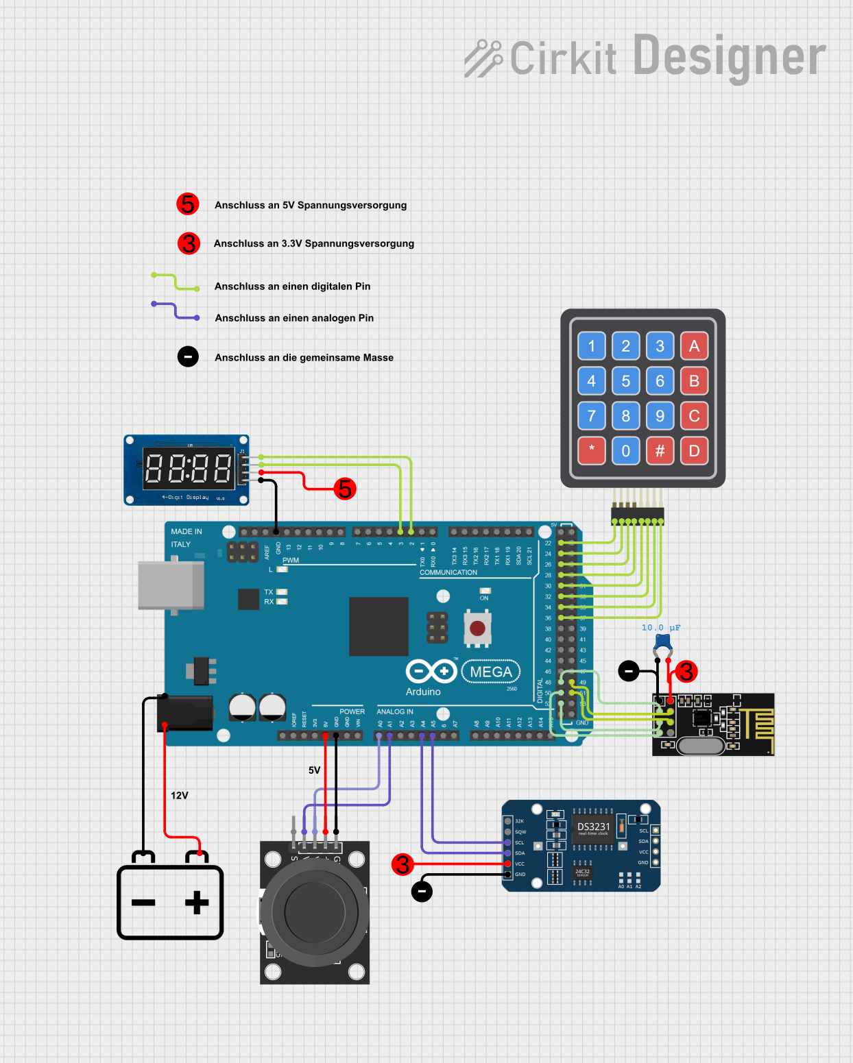
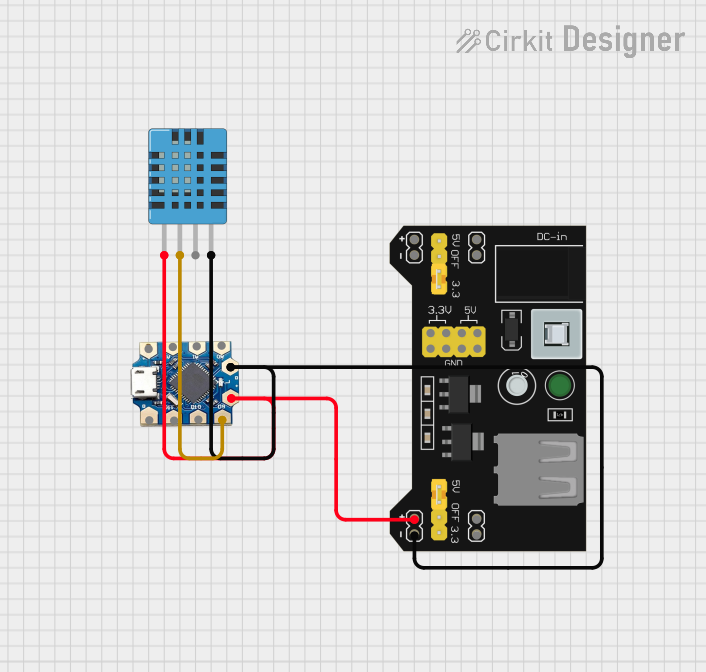

Explore Projects Built with Atmega32
Common Applications and Use Cases
- Home automation systems
- Robotics and motor control
- Data acquisition and logging
- Industrial control systems
- Educational projects and prototyping
Technical Specifications
The Atmega32 microcontroller is packed with features that make it a reliable and efficient choice for embedded systems. Below are its key technical specifications:
| Parameter | Value |
|---|---|
| Architecture | 8-bit AVR RISC |
| Flash Memory | 32 KB |
| SRAM | 2 KB |
| EEPROM | 1 KB |
| Operating Voltage | 4.5V - 5.5V |
| Maximum Clock Speed | 16 MHz |
| I/O Pins | 32 |
| Timers | 3 (Two 8-bit, One 16-bit) |
| ADC Resolution | 10-bit |
| Communication Interfaces | UART, SPI, I2C (TWI) |
| Power Consumption | Low Power Consumption Modes |
| Package Types | DIP-40, TQFP-44, MLF-44 |
Pin Configuration and Descriptions
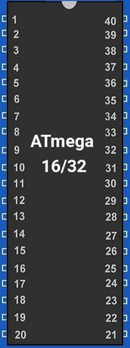
The Atmega32 has 40 pins in its DIP package, which are grouped into four ports (PORTA, PORTB, PORTC, and PORTD). Below is a summary of the pin configuration:
| Pin Number | Pin Name | Description |
|---|---|---|
| 1-8 | PA0-PA7 | PORTA: Analog/Digital I/O or ADC inputs |
| 9 | RESET | Active Low Reset Input |
| 10-17 | PC0-PC7 | PORTC: Digital I/O or JTAG interface |
| 18 | AVCC | Analog Power Supply |
| 19 | AREF | Reference Voltage for ADC |
| 20 | GND | Ground |
| 21-28 | PB0-PB7 | PORTB: Digital I/O or SPI interface |
| 29-36 | PD0-PD7 | PORTD: Digital I/O or UART interface |
| 37 | VCC | Digital Power Supply |
| 38 | XTAL2 | Crystal Oscillator Output |
| 39 | XTAL1 | Crystal Oscillator Input |
| 40 | GND | Ground |
Usage Instructions
The Atmega32 can be used in a variety of circuits, from simple LED blinkers to complex control systems. Below are the steps and considerations for using the Atmega32 in your project:
Basic Circuit Setup
- Power Supply: Connect the VCC pin to a 5V power source and the GND pins to ground.
- Clock Source: Connect an external 16 MHz crystal oscillator to the XTAL1 and XTAL2 pins, along with two 22 pF capacitors to stabilize the clock.
- Reset Pin: Connect a 10 kΩ pull-up resistor to the RESET pin to ensure proper operation.
- I/O Pins: Use the PORTA, PORTB, PORTC, and PORTD pins for digital or analog input/output as required.
Programming the Atmega32
The Atmega32 can be programmed using an ISP (In-System Programmer) or an Arduino as an ISP. Below is an example of how to blink an LED connected to PORTB pin 0 using the Arduino IDE:
// Include the AVR library for direct port manipulation
#include <avr/io.h>
#include <util/delay.h>

int main(void) {
    // Set PORTB pin 0 as output
    DDRB |= (1 << PB0);

    while (1) {
        // Turn on the LED
        PORTB |= (1 << PB0);
        _delay_ms(500); // Wait for 500 ms

        // Turn off the LED
        PORTB &= ~(1 << PB0);
        _delay_ms(500); // Wait for 500 ms
    }

    return 0;
}
Important Considerations
- Voltage Levels: Ensure the operating voltage is within the specified range (4.5V - 5.5V).
- Decoupling Capacitors: Place 0.1 µF capacitors near the power pins to reduce noise.
- Unused Pins: Configure unused pins as inputs with pull-up resistors or outputs to avoid floating states.
- Programming Fuses: Configure the fuses correctly for your application (e.g., clock source, brown-out detection).
Troubleshooting and FAQs
Common Issues and Solutions
Microcontroller Not Responding
- Cause: Incorrect power supply or clock configuration.
- Solution: Verify the power connections and ensure the crystal oscillator is properly connected.
Program Not Running
- Cause: Incorrect fuse settings or programming error.
- Solution: Double-check the fuse settings and reprogram the microcontroller.
ADC Not Working
- Cause: Incorrect reference voltage or uninitialized ADC.
- Solution: Ensure the AREF pin is connected to the correct reference voltage and initialize the ADC in your code.
Communication Failure
- Cause: Incorrect baud rate or wiring.
- Solution: Verify the baud rate settings and check the connections for UART, SPI, or I2C.
FAQs
Q: Can the Atmega32 operate at 3.3V?
A: No, the Atmega32 requires a minimum operating voltage of 4.5V. For 3.3V operation, consider using a different AVR microcontroller.
Q: How do I use the EEPROM?
A: The EEPROM can be accessed using the eeprom_read_byte() and eeprom_write_byte() functions in the AVR library.
Q: Can I use the Atmega32 with an Arduino UNO?
A: Yes, the Atmega32 can be programmed using the Arduino IDE with an external programmer or by using an Arduino UNO as an ISP.
Q: What is the maximum current per I/O pin?
A: Each I/O pin can source or sink up to 40 mA, but the total current for all pins should not exceed 200 mA.