How to Use Wemos D1 R32 (All Pins): Examples, Pinouts, and Specs
Introduction
The Wemos D1 R32 is a versatile microcontroller board based on the powerful ESP32 chip. It combines Wi-Fi and Bluetooth capabilities, making it an excellent choice for Internet of Things (IoT) projects. The board features multiple GPIO pins, allowing seamless interfacing with a wide range of sensors, actuators, and other peripherals. Its compact design and robust performance make it suitable for both hobbyist and professional applications.
Explore Projects Built with Wemos D1 R32 (All Pins)
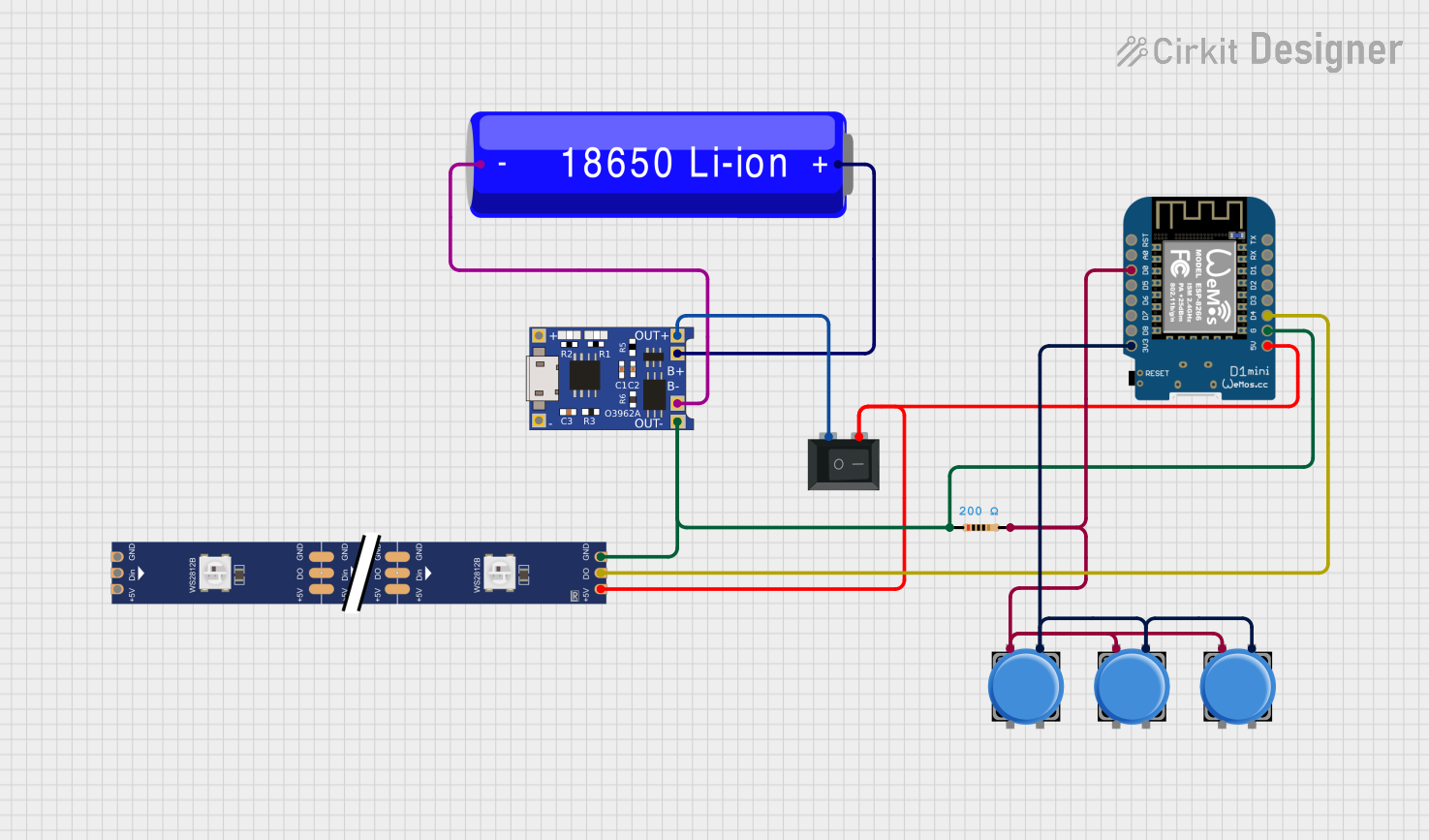
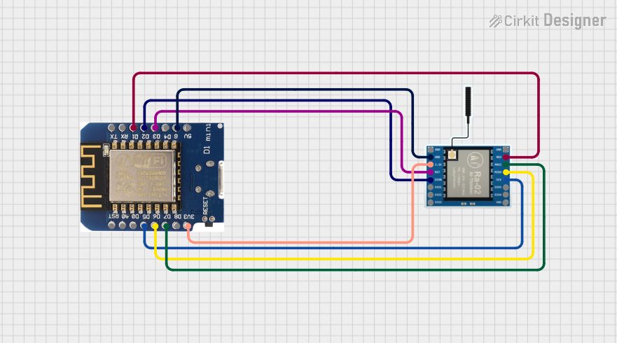
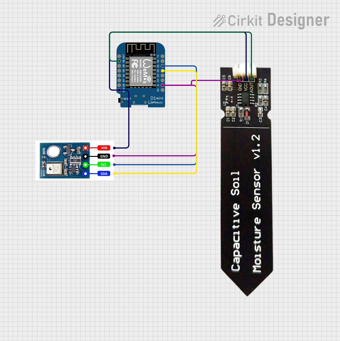

Explore Projects Built with Wemos D1 R32 (All Pins)
Common Applications and Use Cases
- IoT devices and smart home automation
- Wireless sensor networks
- Remote monitoring and control systems
- Robotics and automation
- Prototyping and educational projects
Technical Specifications
The Wemos D1 R32 is designed to provide high performance and flexibility. Below are its key technical details:
| Specification | Details |
|---|---|
| Microcontroller | ESP32 (dual-core, 32-bit Xtensa LX6 processor) |
| Clock Speed | Up to 240 MHz |
| Flash Memory | 4 MB |
| SRAM | 520 KB |
| Wi-Fi | 802.11 b/g/n |
| Bluetooth | Bluetooth 4.2 (Classic and BLE) |
| Operating Voltage | 3.3V |
| Input Voltage (VIN) | 5V (via USB or external power supply) |
| GPIO Pins | 34 (including ADC, DAC, PWM, I2C, SPI, UART) |
| ADC Channels | 18 (12-bit resolution) |
| DAC Channels | 2 |
| Communication Interfaces | UART, SPI, I2C, I2S, CAN |
| USB Interface | Micro-USB |
| Dimensions | 68.6 mm x 53.4 mm |
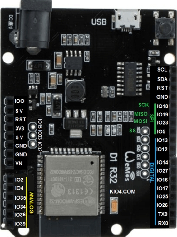
Pin Configuration and Descriptions
The Wemos D1 R32 features a rich set of pins for various functionalities. Below is the pinout description:
| Pin Name | Function | Description |
|---|---|---|
| VIN | Power Input | Accepts 5V input for powering the board. |
| GND | Ground | Common ground for the circuit. |
| 3V3 | Power Output | Provides 3.3V output for external components. |
| GPIO0–GPIO39 | General Purpose I/O | Configurable as digital input/output, ADC, PWM, etc. |
| ADC1/ADC2 | Analog-to-Digital Converter | 12-bit ADC channels for analog input. |
| DAC1/DAC2 | Digital-to-Analog Converter | 8-bit DAC channels for analog output. |
| TX/RX | UART Communication | Serial communication pins (TX: transmit, RX: receive). |
| SCL/SDA | I2C Communication | Clock (SCL) and data (SDA) lines for I2C communication. |
| MOSI/MISO | SPI Communication | SPI data lines (MOSI: Master Out Slave In, MISO: Master In). |
| EN | Enable | Enables or disables the ESP32 chip. |
| BOOT | Boot Mode | Used to enter bootloader mode for firmware flashing. |
Usage Instructions
The Wemos D1 R32 is easy to use and highly adaptable for various projects. Follow the steps below to get started:
Connecting the Board
- Power the Board: Connect the board to your computer or a power source using a Micro-USB cable. Ensure the input voltage is 5V.
- Install Drivers: If required, install the USB-to-serial drivers for the ESP32 chip (e.g., CP210x or CH340 drivers).
- Set Up the IDE: Use the Arduino IDE or ESP-IDF for programming. For Arduino IDE:
- Install the ESP32 board package via the Board Manager.
- Select "Wemos D1 R32" as the board under
Tools > Board.
- Connect Peripherals: Attach sensors, actuators, or other components to the GPIO pins as needed.
Example Code: Blinking an LED
Below is an example of how to blink an LED connected to GPIO2:
// Example: Blink an LED connected to GPIO2 on the Wemos D1 R32

// Define the GPIO pin for the LED
const int ledPin = 2;

void setup() {
  // Set the LED pin as an output
  pinMode(ledPin, OUTPUT);
}

void loop() {
  // Turn the LED on
  digitalWrite(ledPin, HIGH);
  delay(1000); // Wait for 1 second

  // Turn the LED off
  digitalWrite(ledPin, LOW);
  delay(1000); // Wait for 1 second
}
Important Considerations and Best Practices
- Voltage Levels: The GPIO pins operate at 3.3V. Avoid applying 5V directly to the pins to prevent damage.
- Power Supply: Use a stable power source to ensure reliable operation, especially when using Wi-Fi or Bluetooth.
- Pin Multiplexing: Some pins have multiple functions (e.g., ADC, UART). Check the datasheet to avoid conflicts.
- Boot Mode: To upload code, ensure the board is in the correct boot mode. Press and hold the BOOT button if necessary.
Troubleshooting and FAQs
Common Issues and Solutions
Board Not Detected by Computer
- Ensure the USB cable is functional and supports data transfer.
- Install the correct USB-to-serial drivers for your operating system.
Code Upload Fails
- Check the selected board and port in the Arduino IDE.
- Press and hold the BOOT button while uploading the code.
Wi-Fi Connection Issues
- Verify the SSID and password in your code.
- Ensure the Wi-Fi network is within range and operational.
GPIO Pin Not Working
- Confirm the pin is not being used for another function (e.g., ADC, UART).
- Check for wiring issues or incorrect pinMode configuration.
FAQs
Q: Can I power the board using a battery?
A: Yes, you can power the board using a 3.7V LiPo battery connected to the 3V3 pin or a 5V source connected to the VIN pin.
Q: How do I reset the board?
A: Press the RESET button on the board to restart the microcontroller.
Q: Can I use the Wemos D1 R32 with MicroPython?
A: Yes, the ESP32 chip supports MicroPython. Flash the MicroPython firmware to the board and use a compatible IDE like Thonny.
Q: Are all GPIO pins available for use?
A: Not all GPIO pins are available for general use. Some are reserved for specific functions. Refer to the ESP32 datasheet for details.
By following this documentation, you can effectively utilize the Wemos D1 R32 for your projects.