Cirkit Designer Logo
Cirkit Designer
Your all-in-one circuit design IDE
Home / 
Component Documentation

How to Use esp32: Examples, Pinouts, and Specs

Image of esp32
Cirkit Designer LogoDesign with esp32 in Cirkit Designer

Introduction

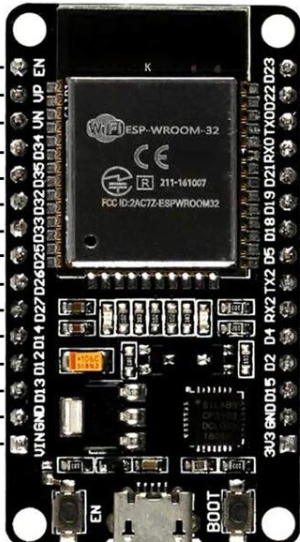
The ESP32, manufactured by Espressif Systems, is a low-cost, low-power system on a chip (SoC) with integrated Wi-Fi and Bluetooth capabilities. It is widely used in Internet of Things (IoT) applications, embedded systems, and smart devices. The ESP32 Dev Module is a development board that simplifies prototyping and development with the ESP32 chip by providing essential components like a USB-to-serial converter, voltage regulator, and pin headers.

Explore Projects Built with esp32

Use Cirkit Designer to design, explore, and prototype these projects online. Some projects support real-time simulation. Click "Open Project" to start designing instantly!
ESP32-Controlled OLED Display and Servo with DotStar LED Strip and Audio Output
Image of Arena 2: A project utilizing esp32 in a practical application
This circuit features an ESP32 microcontroller driving a variety of components. It controls an OLED display for visual output, a DotStar LED strip for lighting effects, a PAM8403 audio amplifier connected to a speaker for sound output, and a PCA9685 PWM Servo Breakout to manage a servo motor. The ESP32 also interfaces with a piezo speaker for additional sound generation, and the circuit is powered by a 18650 Li-ion battery setup with a TP4056 charging module. The ESP32's embedded code handles the display animation on the OLED.
Cirkit Designer LogoOpen Project in Cirkit Designer
ESP32-Based Sensor Monitoring System with OLED Display and E-Stop
Image of MVP_design: A project utilizing esp32 in a practical application
This circuit features an ESP32 microcontroller that interfaces with a variety of sensors and output devices. It is powered by a Lipo battery through a buck converter, ensuring a stable voltage supply. The ESP32 collects data from a DHT11 temperature and humidity sensor and a vibration sensor, controls a buzzer, and displays information on an OLED screen. An emergency stop (E Stop) is connected for safety purposes, allowing the system to be quickly deactivated.
Cirkit Designer LogoOpen Project in Cirkit Designer
ESP32-Based Environmental Monitoring System with Motion Detection
Image of pro: A project utilizing esp32 in a practical application
This circuit features an ESP32 microcontroller on a baseboard that interfaces with a PIR sensor for motion detection, a DHT22 sensor for measuring temperature and humidity, and a BH1750 sensor for detecting ambient light levels. The ESP32 is configured to communicate with the BH1750 using I2C protocol, with GPIO22 and GPIO21 serving as the SCL and SDA lines, respectively. Power is supplied to the sensors from the ESP32's voltage output pins, and sensor outputs are connected to designated GPIO pins for data acquisition.
Cirkit Designer LogoOpen Project in Cirkit Designer
ESP32-Based Smart Weather Station with Wi-Fi Connectivity
Image of flowchart 3D: A project utilizing esp32 in a practical application
This circuit features an ESP32 microcontroller interfacing with various sensors and modules, including a DHT22 temperature and humidity sensor, an ESP32 CAM for image capture, an I2C LCD screen for display, a load cell with an HX711 interface for weight measurement, and a buzzer for audio alerts. The ESP32 handles data acquisition, processing, and communication with these peripherals to create a multi-functional monitoring and alert system.
Cirkit Designer LogoOpen Project in Cirkit Designer

Explore Projects Built with esp32

Use Cirkit Designer to design, explore, and prototype these projects online. Some projects support real-time simulation. Click "Open Project" to start designing instantly!
Image of Arena 2: A project utilizing esp32 in a practical application
ESP32-Controlled OLED Display and Servo with DotStar LED Strip and Audio Output
This circuit features an ESP32 microcontroller driving a variety of components. It controls an OLED display for visual output, a DotStar LED strip for lighting effects, a PAM8403 audio amplifier connected to a speaker for sound output, and a PCA9685 PWM Servo Breakout to manage a servo motor. The ESP32 also interfaces with a piezo speaker for additional sound generation, and the circuit is powered by a 18650 Li-ion battery setup with a TP4056 charging module. The ESP32's embedded code handles the display animation on the OLED.
Cirkit Designer LogoOpen Project in Cirkit Designer
Image of MVP_design: A project utilizing esp32 in a practical application
ESP32-Based Sensor Monitoring System with OLED Display and E-Stop
This circuit features an ESP32 microcontroller that interfaces with a variety of sensors and output devices. It is powered by a Lipo battery through a buck converter, ensuring a stable voltage supply. The ESP32 collects data from a DHT11 temperature and humidity sensor and a vibration sensor, controls a buzzer, and displays information on an OLED screen. An emergency stop (E Stop) is connected for safety purposes, allowing the system to be quickly deactivated.
Cirkit Designer LogoOpen Project in Cirkit Designer
Image of pro: A project utilizing esp32 in a practical application
ESP32-Based Environmental Monitoring System with Motion Detection
This circuit features an ESP32 microcontroller on a baseboard that interfaces with a PIR sensor for motion detection, a DHT22 sensor for measuring temperature and humidity, and a BH1750 sensor for detecting ambient light levels. The ESP32 is configured to communicate with the BH1750 using I2C protocol, with GPIO22 and GPIO21 serving as the SCL and SDA lines, respectively. Power is supplied to the sensors from the ESP32's voltage output pins, and sensor outputs are connected to designated GPIO pins for data acquisition.
Cirkit Designer LogoOpen Project in Cirkit Designer
Image of flowchart 3D: A project utilizing esp32 in a practical application
ESP32-Based Smart Weather Station with Wi-Fi Connectivity
This circuit features an ESP32 microcontroller interfacing with various sensors and modules, including a DHT22 temperature and humidity sensor, an ESP32 CAM for image capture, an I2C LCD screen for display, a load cell with an HX711 interface for weight measurement, and a buzzer for audio alerts. The ESP32 handles data acquisition, processing, and communication with these peripherals to create a multi-functional monitoring and alert system.
Cirkit Designer LogoOpen Project in Cirkit Designer

Common Applications and Use Cases

  • IoT devices (e.g., smart home systems, sensors, and actuators)
  • Wireless communication (Wi-Fi and Bluetooth)
  • Wearable devices
  • Robotics and automation
  • Data logging and remote monitoring
  • Home automation and smart appliances

Technical Specifications

Key Technical Details

  • Manufacturer: Espressif Systems
  • Part ID: ESP32 Dev Module
  • Processor: Dual-core Xtensa® 32-bit LX6 microprocessor
  • Clock Speed: Up to 240 MHz
  • Flash Memory: 4 MB (varies by model)
  • SRAM: 520 KB
  • Wireless Connectivity: Wi-Fi 802.11 b/g/n, Bluetooth 4.2 (Classic and BLE)
  • Operating Voltage: 3.3V
  • Input Voltage (via USB): 5V
  • GPIO Pins: 34 (multipurpose, including ADC, DAC, PWM, I2C, SPI, UART)
  • ADC Resolution: 12-bit
  • DAC Resolution: 8-bit
  • Power Consumption: Ultra-low power consumption in deep sleep mode (~10 µA)

Pin Configuration and Descriptions

The ESP32 Dev Module has multiple GPIO pins, each capable of serving various functions. Below is a table summarizing the key pins and their descriptions:

Pin Name Function Description
VIN Power Input Input voltage (5V) when powering via USB or external source.
3V3 Power Output Regulated 3.3V output from the onboard voltage regulator.
GND Ground Common ground for the circuit.
EN Enable Active-high pin to enable or reset the chip.
GPIO0 Boot Mode Selection Used to enter bootloader mode during programming.
GPIO2 General Purpose I/O Can be used as a standard GPIO pin.
GPIO12-39 General Purpose I/O Multipurpose pins for ADC, DAC, PWM, I2C, SPI, UART, etc.
TXD0, RXD0 UART0 (Serial Communication) Default UART pins for serial communication.
SCL, SDA I2C Communication Default pins for I2C communication (can be reassigned).
SPI Pins SPI Communication Includes MOSI, MISO, SCK, and CS for SPI communication.
ADC Pins Analog-to-Digital Converter 12-bit ADC pins for reading analog signals.
DAC Pins Digital-to-Analog Converter 8-bit DAC pins for generating analog signals.

Note: Not all GPIO pins are available for general use. Some are reserved for specific functions or have limitations. Refer to the ESP32 datasheet for detailed pin capabilities.

Usage Instructions

How to Use the ESP32 in a Circuit

  1. Powering the ESP32:

    • Connect the ESP32 to a computer or USB power source using a micro-USB cable.
    • Alternatively, supply 5V to the VIN pin or 3.3V to the 3V3 pin.
  2. Programming the ESP32:

    • Install the Arduino IDE and add the ESP32 board support package.
    • Select "ESP32 Dev Module" from the Tools > Board menu.
    • Connect the ESP32 to your computer and select the appropriate COM port.
  3. Connecting Peripherals:

    • Use GPIO pins to connect sensors, actuators, or other peripherals.
    • Ensure proper voltage levels (3.3V logic) to avoid damaging the ESP32.
  4. Uploading Code:

    • Write your code in the Arduino IDE or another supported environment.
    • Press the "Upload" button to compile and upload the code to the ESP32.
    • If the upload fails, press and hold the "BOOT" button on the ESP32 during the upload process.

Example Code: Blinking an LED

The following example demonstrates how to blink an LED connected to GPIO2 of the ESP32:

// Define the GPIO pin where the LED is connected
const int ledPin = 2;

void setup() {
  // Set the LED pin as an output
  pinMode(ledPin, OUTPUT);
}

void loop() {
  // Turn the LED on
  digitalWrite(ledPin, HIGH);
  delay(1000); // Wait for 1 second

  // Turn the LED off
  digitalWrite(ledPin, LOW);
  delay(1000); // Wait for 1 second
}

Important Considerations and Best Practices

  • Voltage Levels: The ESP32 operates at 3.3V logic. Avoid connecting 5V signals directly to GPIO pins.
  • Power Supply: Ensure a stable power supply to avoid unexpected resets or malfunctions.
  • Deep Sleep Mode: Use deep sleep mode to minimize power consumption in battery-powered applications.
  • Boot Mode: If the ESP32 fails to boot, check the state of GPIO0 and EN pins.

Troubleshooting and FAQs

Common Issues and Solutions

  1. Problem: The ESP32 is not detected by the computer.
    Solution:

    • Ensure the USB cable is functional and supports data transfer.
    • Install the correct USB-to-serial driver (e.g., CP2102 or CH340).
  2. Problem: Code upload fails with a timeout error.
    Solution:

    • Press and hold the "BOOT" button during the upload process.
    • Check the selected COM port and board type in the Arduino IDE.
  3. Problem: The ESP32 resets unexpectedly.
    Solution:

    • Verify the power supply is stable and sufficient.
    • Avoid excessive current draw from GPIO pins.
  4. Problem: Wi-Fi connection fails.
    Solution:

    • Double-check the SSID and password in your code.
    • Ensure the Wi-Fi network is within range and operational.

FAQs

  • Q: Can I use the ESP32 with 5V sensors?
    A: Yes, but you need a level shifter to convert 5V signals to 3.3V.

  • Q: How do I reset the ESP32?
    A: Press the "EN" button on the development board to reset the chip.

  • Q: Can the ESP32 be powered by batteries?
    A: Yes, the ESP32 can be powered by batteries, but ensure the voltage is regulated to 3.3V or 5V.

  • Q: How many devices can the ESP32 connect to via Bluetooth?
    A: The ESP32 supports up to 7 simultaneous Bluetooth connections in Classic mode.

This documentation provides a comprehensive guide to using the ESP32 Dev Module for various applications. For more advanced features, refer to the official Espressif documentation.