How to Use nMOS Transistor (MOSFET): Examples, Pinouts, and Specs
Introduction
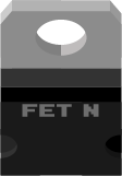
An nMOS transistor, also known as an n-channel metal-oxide-semiconductor field-effect transistor (MOSFET), is a fundamental electronic component widely used for amplifying or switching electronic signals. It operates by controlling the flow of electrons through a channel with an applied voltage. nMOS transistors are prevalent in digital circuits, power management applications, and as switches in various electronic devices.
Explore Projects Built with nMOS Transistor (MOSFET)
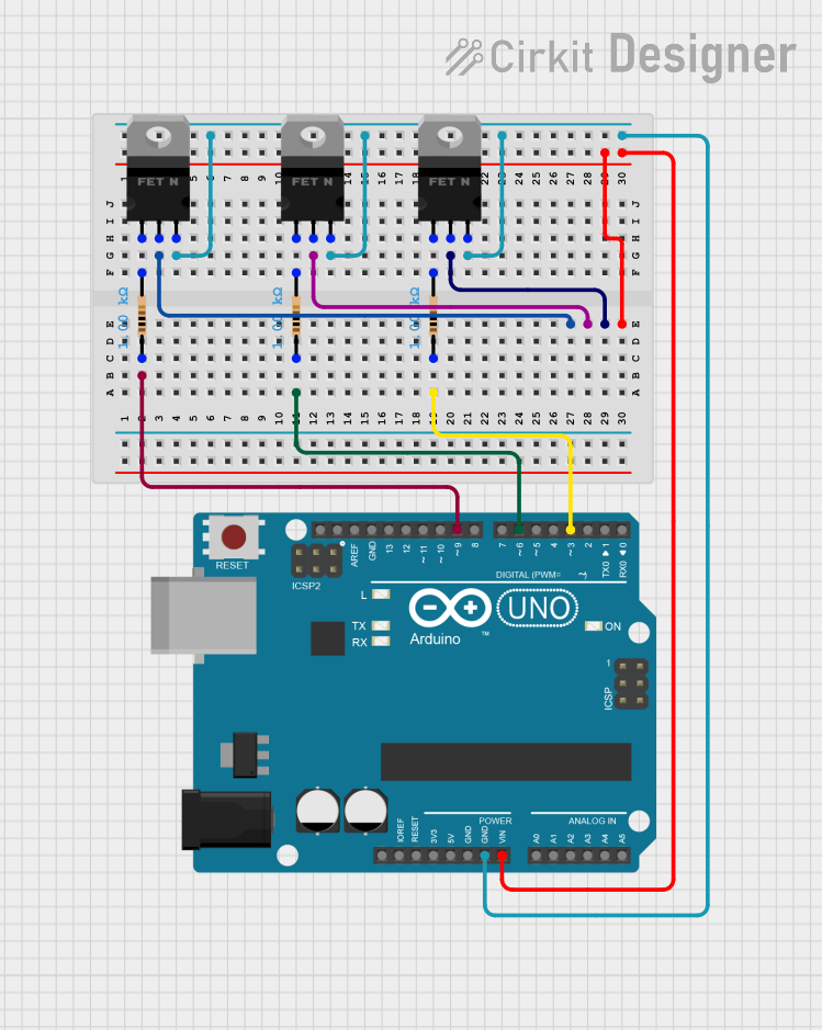

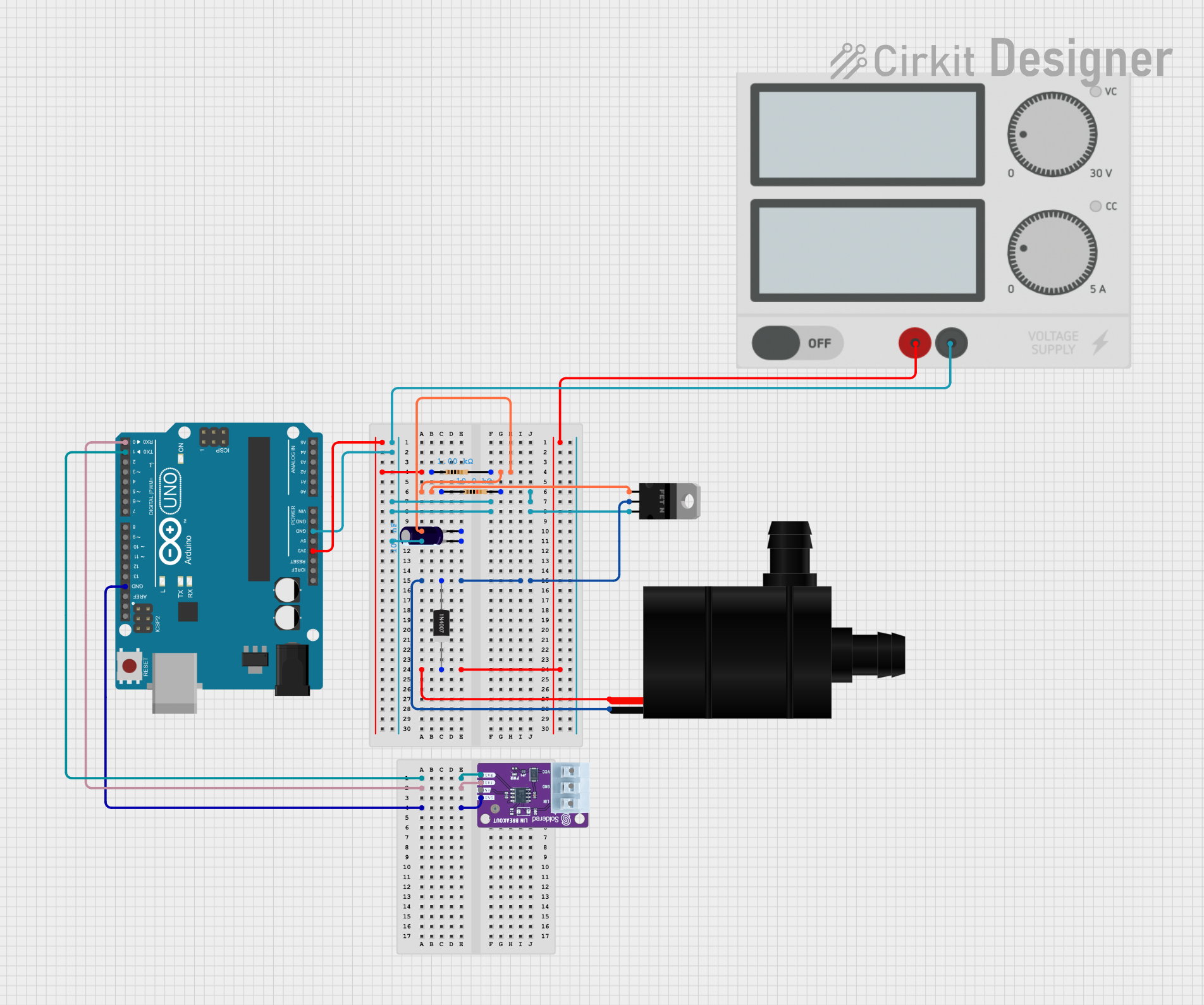
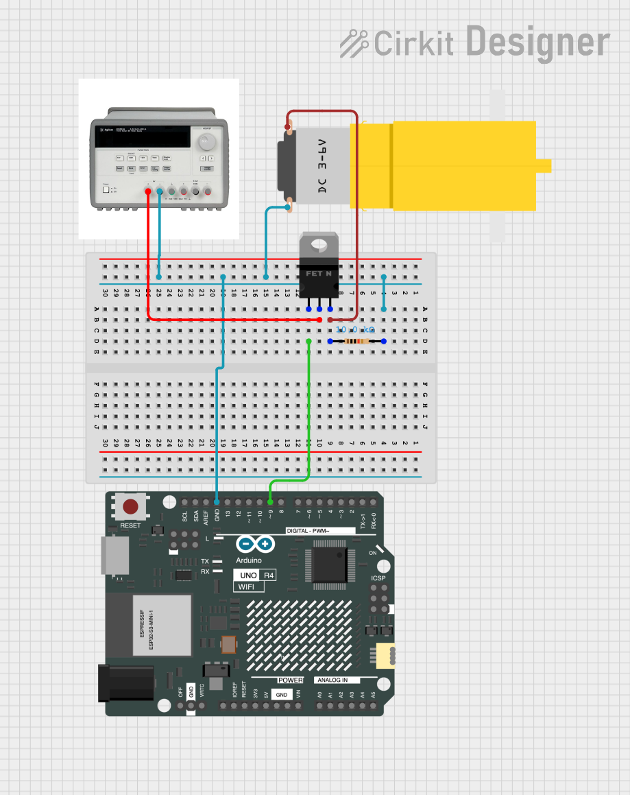
Explore Projects Built with nMOS Transistor (MOSFET)
Technical Specifications
Key Technical Details
| Parameter | Description | Typical Values |
|---|---|---|
| VDS | Drain-to-Source Voltage | Up to 100V or higher |
| ID | Drain Current | Up to 10A or higher |
| VGS | Gate-to-Source Voltage | ±10V to ±20V |
| RDS(on) | Drain-to-Source On Resistance | Few milliohms to Ohms |
| PD | Power Dissipation | Up to several Watts |
| Qg | Total Gate Charge | Tens to hundreds of nC |
Pin Configuration and Descriptions
| Pin Name | Description |
|---|---|
| Gate (G) | Controls the flow of current through the channel |
| Drain (D) | Where the controlled current leaves the transistor |
| Source (S) | Where the controlled current enters the transistor |
Usage Instructions
How to Use the Component in a Circuit
- Biasing the Gate: Apply a voltage to the gate relative to the source to control the current flow through the drain-source channel.
- Load Connection: Connect the load to the drain terminal, ensuring that the voltage and current ratings do not exceed the transistor's specifications.
- Source Terminal: Connect the source terminal to the ground or the negative side of the power supply.
Important Considerations and Best Practices
- Gate Protection: Use a gate resistor to limit the inrush current and a gate-source Zener diode for overvoltage protection.
- Heat Dissipation: Ensure proper heat sinking to manage power dissipation and prevent overheating.
- Drive Voltage: Provide sufficient gate-source voltage (VGS) to fully turn on the MOSFET (usually 10V for standard nMOS).
- Switching Speed: Consider the gate charge (Qg) and gate-source capacitance when designing for high-speed switching applications.
Troubleshooting and FAQs
Common Issues
- MOSFET Not Turning On: Check if the gate-source voltage is above the threshold voltage. Ensure the gate is not shorted to the source.
- Overheating: Verify that the power dissipation is within limits and that the heat sink is adequate.
- Unexpected Switching: Noise in the circuit can cause unintended switching. Ensure proper decoupling and shielding.
Solutions and Tips
- Gate Drive Circuit: Use a dedicated gate driver for better control and to provide the required gate charge.
- Gate Pull-Down Resistor: A pull-down resistor on the gate can prevent floating gate issues and accidental turn-ons.
- Snubber Circuit: A snubber circuit across the drain and source can reduce voltage spikes during switching.
FAQs
Q: Can I drive an nMOS directly from a microcontroller? A: Yes, if the microcontroller can provide sufficient gate voltage. Otherwise, use a gate driver.
Q: What is the maximum frequency for switching an nMOS? A: It depends on the specific MOSFET's gate charge and the driver's capability. Check the datasheet for switching characteristics.
Q: How do I choose the right nMOS for my application? A: Consider the maximum drain-source voltage, drain current, power dissipation, and switching speed required for your application.
Example Code for Arduino UNO
Below is an example code snippet for using an nMOS transistor to switch a high-power LED on and off with an Arduino UNO.
const int ledPin = 3; // Connect the LED+resistor to the Drain of the MOSFET
const int gatePin = 2; // Connect to the Gate of the MOSFET

void setup() {
  pinMode(ledPin, OUTPUT);
  pinMode(gatePin, OUTPUT);
}

void loop() {
  digitalWrite(gatePin, HIGH); // Turn on the LED
  delay(1000);                 // Wait for 1 second
  digitalWrite(gatePin, LOW);  // Turn off the LED
  delay(1000);                 // Wait for 1 second
}
Note: Ensure that the gate threshold voltage of the nMOS is compatible with the output voltage level of the Arduino pin. If not, use a gate driver or a level shifter.