Cirkit Designer Logo
Cirkit Designer
Your all-in-one circuit design IDE
Home / 
Component Documentation

How to Use Servo: Examples, Pinouts, and Specs

Image of Servo
Cirkit Designer LogoDesign with Servo in Cirkit Designer

Introduction

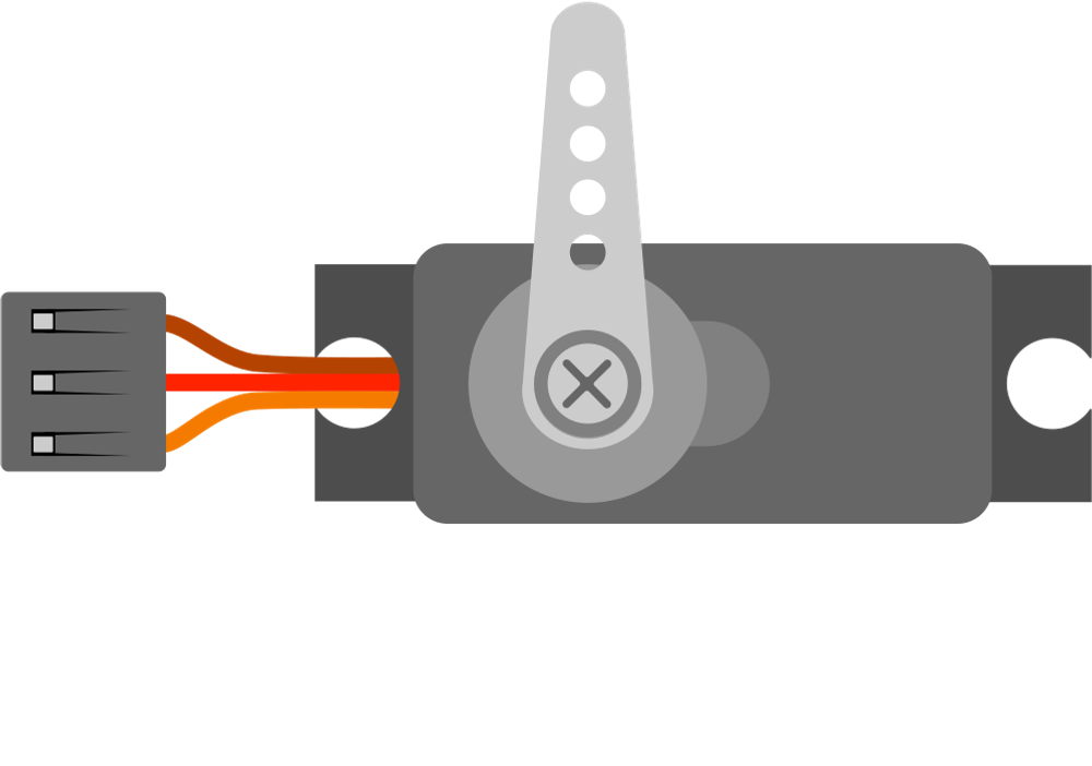
A servo is a rotary actuator that allows for precise control of angular position, velocity, and acceleration. It consists of a motor coupled to a sensor for position feedback, along with a control circuit. Servos are widely used in robotics, automation, remote-controlled vehicles, and industrial machinery due to their ability to provide accurate and repeatable motion.

Explore Projects Built with Servo

Use Cirkit Designer to design, explore, and prototype these projects online. Some projects support real-time simulation. Click "Open Project" to start designing instantly!
Arduino Mega 2560 Controlled Multi-Servo Random Positioning System
Image of robotic: A project utilizing Servo in a practical application
This circuit consists of an Arduino Mega 2560 microcontroller connected to twelve servo motors, each individually controlled by a distinct PWM pin on the Arduino. The servos are powered by a single Polymer Lithium Ion Battery, with all servos sharing a common power (VCC) and ground (GND) connection. The embedded code on the Arduino is designed to randomly position each servo within a 0 to 180-degree range, with a random delay between movements, demonstrating a multi-servo control system possibly for applications like robotics or animatronics.
Cirkit Designer LogoOpen Project in Cirkit Designer
Arduino UNO Servo Motor Controller
Image of Test project: A project utilizing Servo in a practical application
This circuit consists of an Arduino UNO microcontroller connected to a servo motor. The Arduino provides power (5V and GND) to the servo and controls its position through a pulse signal on pin D9. The embedded code on the Arduino is programmed to smoothly move the servo between 0 and 180 degrees, creating a sweeping motion.
Cirkit Designer LogoOpen Project in Cirkit Designer
Arduino UNO Controlled Servo Motor
Image of lblblblb: A project utilizing Servo in a practical application
This circuit consists of an Arduino UNO microcontroller connected to a servo motor. The Arduino provides power (5V) and ground connections to the servo, as well as a control signal through one of its digital pins (D6). The embedded code on the Arduino is set up to control the servo's position, sending it to a fixed angle upon each loop iteration.
Cirkit Designer LogoOpen Project in Cirkit Designer
Arduino-Controlled Multi-Servo System
Image of Mind controlled robotic arm: A project utilizing Servo in a practical application
This circuit consists of an Arduino UNO microcontroller connected to five servo motors. The servos are powered by the Arduino's 5V output and share a common ground. Each servo's PWM control pin is individually connected to a digital pin on the Arduino (D8, D9, D10, D11, D12), allowing for independent control of each servo's position. The Arduino is also connected to a laptop via USB for programming and power.
Cirkit Designer LogoOpen Project in Cirkit Designer

Explore Projects Built with Servo

Use Cirkit Designer to design, explore, and prototype these projects online. Some projects support real-time simulation. Click "Open Project" to start designing instantly!
Image of robotic: A project utilizing Servo in a practical application
Arduino Mega 2560 Controlled Multi-Servo Random Positioning System
This circuit consists of an Arduino Mega 2560 microcontroller connected to twelve servo motors, each individually controlled by a distinct PWM pin on the Arduino. The servos are powered by a single Polymer Lithium Ion Battery, with all servos sharing a common power (VCC) and ground (GND) connection. The embedded code on the Arduino is designed to randomly position each servo within a 0 to 180-degree range, with a random delay between movements, demonstrating a multi-servo control system possibly for applications like robotics or animatronics.
Cirkit Designer LogoOpen Project in Cirkit Designer
Image of Test project: A project utilizing Servo in a practical application
Arduino UNO Servo Motor Controller
This circuit consists of an Arduino UNO microcontroller connected to a servo motor. The Arduino provides power (5V and GND) to the servo and controls its position through a pulse signal on pin D9. The embedded code on the Arduino is programmed to smoothly move the servo between 0 and 180 degrees, creating a sweeping motion.
Cirkit Designer LogoOpen Project in Cirkit Designer
Image of lblblblb: A project utilizing Servo in a practical application
Arduino UNO Controlled Servo Motor
This circuit consists of an Arduino UNO microcontroller connected to a servo motor. The Arduino provides power (5V) and ground connections to the servo, as well as a control signal through one of its digital pins (D6). The embedded code on the Arduino is set up to control the servo's position, sending it to a fixed angle upon each loop iteration.
Cirkit Designer LogoOpen Project in Cirkit Designer
Image of Mind controlled robotic arm: A project utilizing Servo in a practical application
Arduino-Controlled Multi-Servo System
This circuit consists of an Arduino UNO microcontroller connected to five servo motors. The servos are powered by the Arduino's 5V output and share a common ground. Each servo's PWM control pin is individually connected to a digital pin on the Arduino (D8, D9, D10, D11, D12), allowing for independent control of each servo's position. The Arduino is also connected to a laptop via USB for programming and power.
Cirkit Designer LogoOpen Project in Cirkit Designer

Common Applications and Use Cases

  • Robotics: Controlling robotic arms, grippers, and joints.
  • RC Vehicles: Steering and throttle control in remote-controlled cars, boats, and planes.
  • Automation: Positioning systems in conveyor belts and manufacturing equipment.
  • DIY Projects: Automated doors, camera gimbals, and hobbyist creations.
  • Aerospace: Flight control surfaces in model aircraft.

Technical Specifications

Below are the general technical specifications for a standard hobby servo. Note that specific models may vary slightly.

Key Technical Details

  • Operating Voltage: 4.8V to 6.0V (typical range)
  • Torque: 1.5 kg-cm to 20 kg-cm (varies by model)
  • Speed: 0.1 to 0.2 seconds per 60° (at 6.0V)
  • Control Signal: Pulse Width Modulation (PWM)
  • Angle Range: 0° to 180° (standard), some models support 360° rotation
  • Connector: 3-pin (Signal, VCC, GND)

Pin Configuration and Descriptions

The servo typically has a 3-pin connector with the following pinout:

Pin Number Name Description
1 Signal Receives PWM signal for position control
2 VCC Power supply (4.8V to 6.0V)
3 GND Ground connection

Usage Instructions

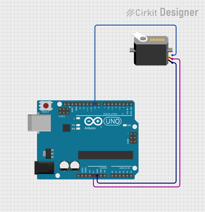
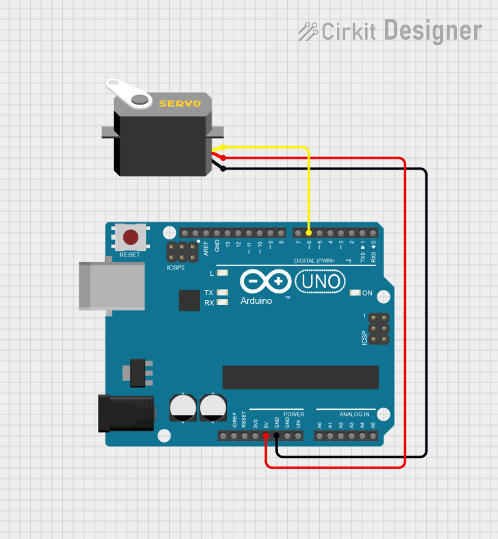
How to Use the Servo in a Circuit

  1. Connect the Servo:

    • Connect the Signal pin to a PWM-capable pin on your microcontroller (e.g., Arduino).
    • Connect the VCC pin to a 5V power source.
    • Connect the GND pin to the ground of your circuit.
  2. Generate PWM Signal:

    • Use a microcontroller to generate a PWM signal. The pulse width determines the servo's position:
      • 1 ms pulse: 0° position
      • 1.5 ms pulse: 90° position (center)
      • 2 ms pulse: 180° position
  3. Power Considerations:

    • Ensure the power supply can handle the servo's current draw, especially under load.
    • For high-torque servos, use an external power source instead of relying on the microcontroller's 5V pin.

Example Code for Arduino UNO

Below is an example of how to control a servo using an Arduino UNO and the Servo library:

#include <Servo.h> // Include the Servo library

Servo myServo; // Create a Servo object to control the servo

void setup() {
  myServo.attach(9); // Attach the servo to pin 9 on the Arduino
}

void loop() {
  myServo.write(0); // Move the servo to 0 degrees
  delay(1000);      // Wait for 1 second

  myServo.write(90); // Move the servo to 90 degrees (center position)
  delay(1000);       // Wait for 1 second

  myServo.write(180); // Move the servo to 180 degrees
  delay(1000);        // Wait for 1 second
}

Important Considerations and Best Practices

  • Avoid Overloading: Do not exceed the servo's torque rating to prevent damage.
  • Stable Power Supply: Use a capacitor or external power source to avoid voltage drops.
  • PWM Accuracy: Ensure the microcontroller generates accurate PWM signals for smooth operation.
  • Mechanical Limits: Avoid forcing the servo beyond its physical range to prevent damage.

Troubleshooting and FAQs

Common Issues and Solutions

  1. Servo Not Moving:

    • Cause: Incorrect wiring or insufficient power.
    • Solution: Double-check connections and ensure the power supply meets the servo's requirements.
  2. Jittery or Erratic Movement:

    • Cause: Noise in the PWM signal or unstable power supply.
    • Solution: Use a decoupling capacitor near the servo and ensure a clean PWM signal.
  3. Overheating:

    • Cause: Prolonged operation under high load or stalled motor.
    • Solution: Reduce the load or use a higher-torque servo.
  4. Servo Not Centering Properly:

    • Cause: Calibration issue or incorrect PWM signal.
    • Solution: Verify the PWM pulse width and recalibrate if necessary.

FAQs

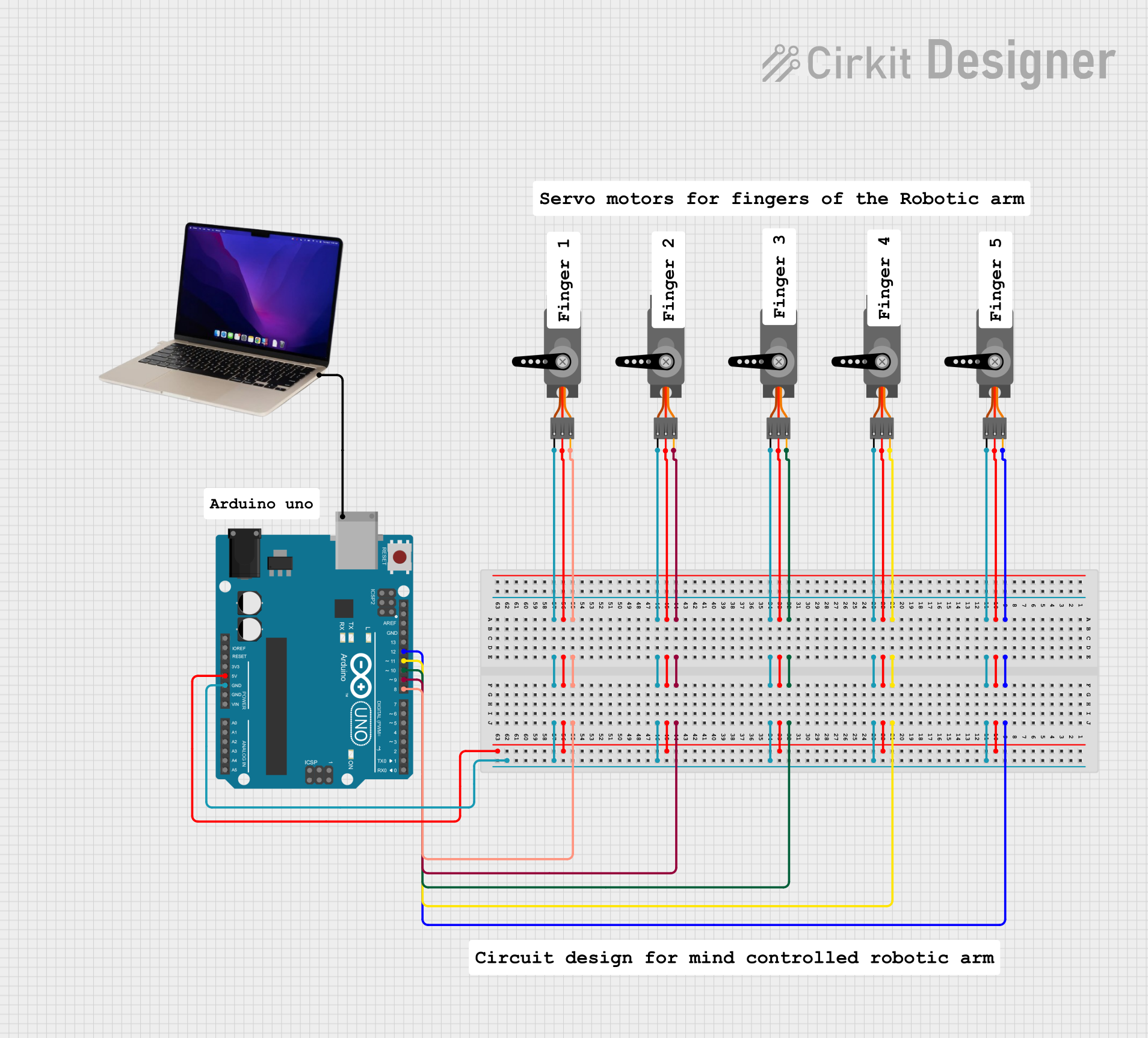
  • Can I control multiple servos with one Arduino? Yes, you can control multiple servos using different PWM-capable pins. Use the Servo library to manage multiple servos.

  • What happens if I exceed the servo's voltage rating? Exceeding the voltage rating can damage the servo's internal components. Always stay within the specified range.

  • Can I use a servo for continuous rotation? Some servos are designed for continuous rotation. These are modified to interpret PWM signals as speed and direction rather than position.

  • Why does my servo make a buzzing noise? A buzzing noise indicates the servo is under load or struggling to maintain its position. Check for mechanical obstructions or excessive torque requirements.