Cirkit Designer
Your all-in-one circuit design IDE
Home /
Component Documentation
How to Use MOTOR CONTROLLER: Examples, Pinouts, and Specs
Introduction
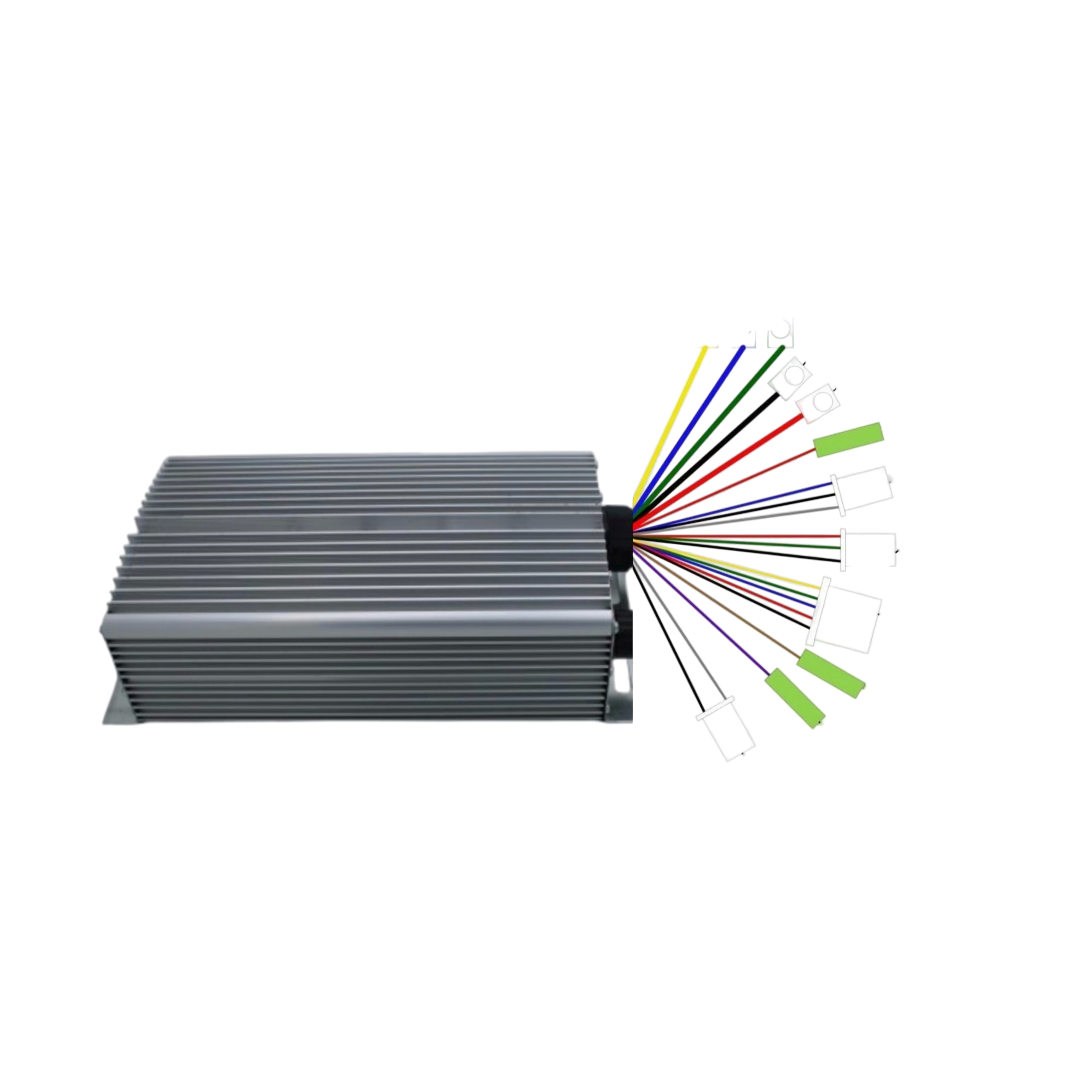
The DAIKIN VGG Motor Controller is a versatile device designed to regulate the performance of electric motors by controlling their speed, torque, and direction. This motor controller is suitable for a wide range of applications, including robotics, electric vehicles, and industrial machinery. Its robust design and advanced features make it an ideal choice for both hobbyists and professionals.
Explore Projects Built with MOTOR CONTROLLER
ESP8266 Controlled Robotics Platform with GPS, IR, and GSM Features
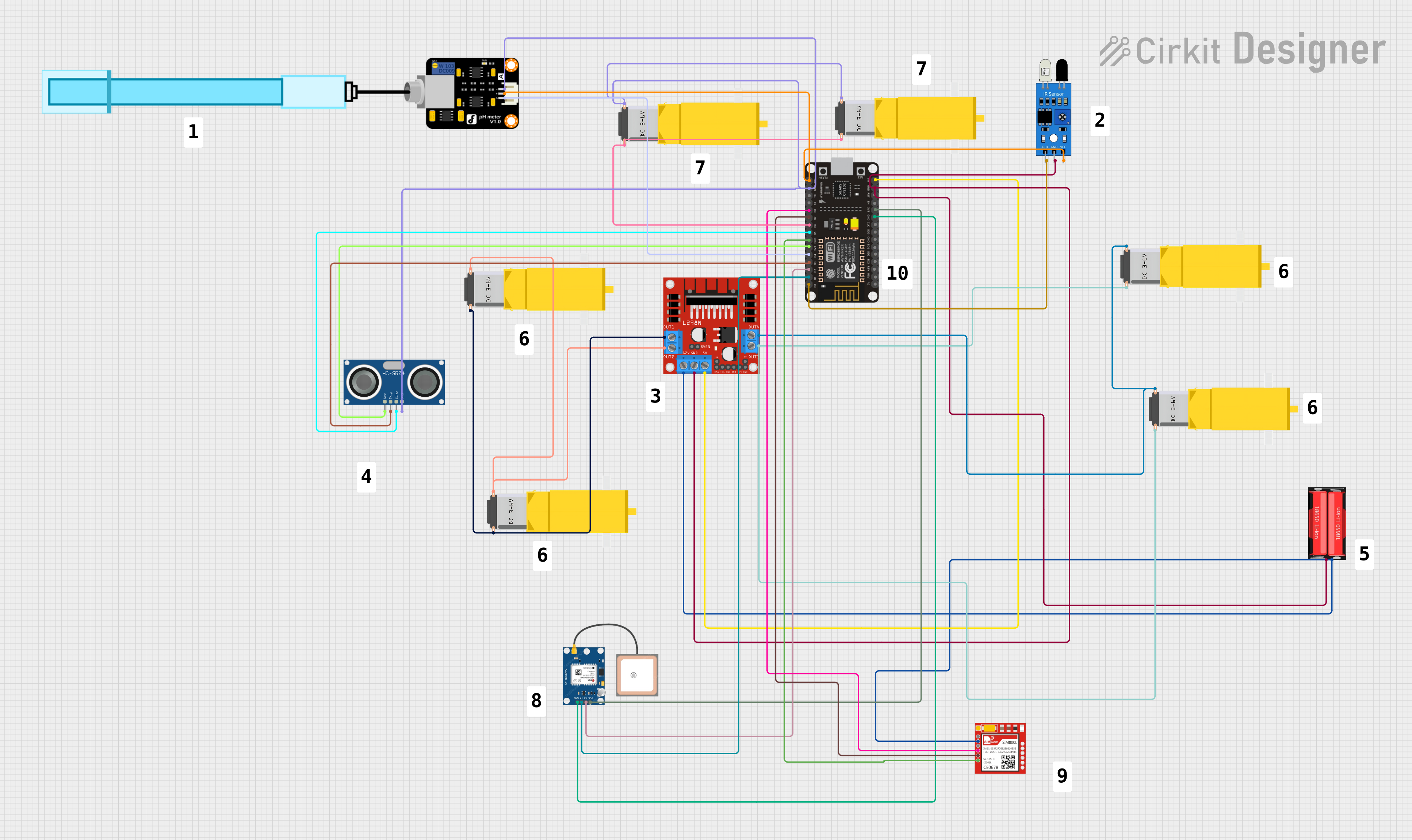
This is a microcontroller-based control system designed for a mobile robotic platform with environmental sensing, location tracking, and GSM communication capabilities. It includes motor control for actuation, various sensors for data acquisition, and a battery for power supply.
Battery-Powered Robotic Vehicle with STM32 and L298N Motor Driver
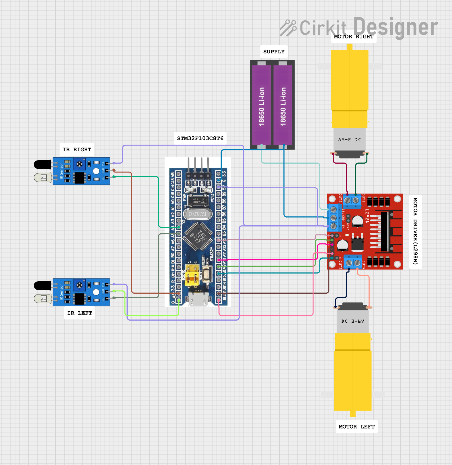
This circuit is a motor control system that uses an STM32F103C8T6 microcontroller to control two DC motors via an L298N motor driver. The system also includes two IR sensors for obstacle detection, powered by a 18650 Li-ion battery pack.
Arduino-Controlled Motor System with Bluetooth Connectivity
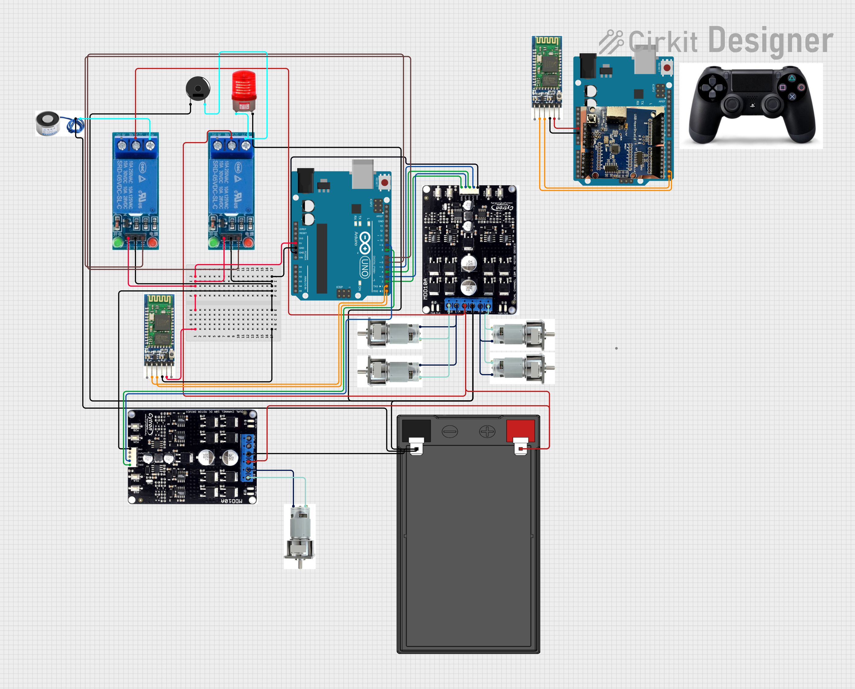
This is a motor control system with wireless communication capabilities, designed to operate multiple motors via Cytron motor drivers, controlled by Arduino UNOs. It includes relays for activating a light and buzzer, and uses Bluetooth for remote operation. The system's software is in the initial stages of development.
ESP32 and L298N Motor Driver Controlled Battery-Powered Robotic Car

This circuit is a motor control system powered by a 12V battery, utilizing an L298N motor driver to control four DC gearmotors. An ESP32 microcontroller is used to send control signals to the motor driver, enabling precise control of the motors for applications such as a robotic vehicle.
Explore Projects Built with MOTOR CONTROLLER
ESP8266 Controlled Robotics Platform with GPS, IR, and GSM Features
This is a microcontroller-based control system designed for a mobile robotic platform with environmental sensing, location tracking, and GSM communication capabilities. It includes motor control for actuation, various sensors for data acquisition, and a battery for power supply.
Battery-Powered Robotic Vehicle with STM32 and L298N Motor Driver
This circuit is a motor control system that uses an STM32F103C8T6 microcontroller to control two DC motors via an L298N motor driver. The system also includes two IR sensors for obstacle detection, powered by a 18650 Li-ion battery pack.
Arduino-Controlled Motor System with Bluetooth Connectivity
This is a motor control system with wireless communication capabilities, designed to operate multiple motors via Cytron motor drivers, controlled by Arduino UNOs. It includes relays for activating a light and buzzer, and uses Bluetooth for remote operation. The system's software is in the initial stages of development.
ESP32 and L298N Motor Driver Controlled Battery-Powered Robotic Car
This circuit is a motor control system powered by a 12V battery, utilizing an L298N motor driver to control four DC gearmotors. An ESP32 microcontroller is used to send control signals to the motor driver, enabling precise control of the motors for applications such as a robotic vehicle.
Technical Specifications
Key Technical Details
| Parameter | Value |
|---|---|
| Manufacturer | DAIKIN |
| Part ID | VGG |
| Input Voltage | 12V - 48V DC |
| Continuous Current | 30A |
| Peak Current | 50A |
| Control Signal | PWM (Pulse Width Modulation) |
| Operating Temperature | -20°C to 85°C |
| Dimensions | 100mm x 60mm x 30mm |
| Weight | 150g |
Pin Configuration and Descriptions
| Pin Number | Pin Name | Description |
|---|---|---|
| 1 | VCC | Power Supply Input (12V - 48V DC) |
| 2 | GND | Ground |
| 3 | IN1 | Control Signal Input 1 (PWM) |
| 4 | IN2 | Control Signal Input 2 (PWM) |
| 5 | OUT1 | Motor Output 1 |
| 6 | OUT2 | Motor Output 2 |
| 7 | EN | Enable Pin (Active High) |
| 8 | FG | Fault/Status Output (Open Drain) |
Usage Instructions
How to Use the Component in a Circuit
Power Supply Connection:
- Connect the VCC pin to a DC power supply ranging from 12V to 48V.
- Connect the GND pin to the ground of the power supply.
Motor Connection:
- Connect the motor terminals to the OUT1 and OUT2 pins.
Control Signal Connection:
- Connect the PWM control signals to the IN1 and IN2 pins.
- Use a microcontroller (e.g., Arduino UNO) to generate the PWM signals.
Enable Pin:
- Connect the EN pin to a digital output pin of the microcontroller.
- Set the EN pin high to enable the motor controller.
Fault/Status Output:
- Connect the FG pin to a digital input pin of the microcontroller to monitor the status.
Important Considerations and Best Practices
- Ensure that the power supply voltage is within the specified range (12V - 48V DC).
- Use appropriate heat sinks or cooling mechanisms if the motor controller operates at high currents for extended periods.
- Implement proper filtering and decoupling capacitors to minimize noise and ensure stable operation.
- Avoid sudden changes in control signals to prevent damage to the motor and controller.
Example Code for Arduino UNO
// Example code to control the DAIKIN VGG Motor Controller using Arduino UNO

const int EN_PIN = 7;  // Enable pin connected to digital pin 7
const int IN1_PIN = 9; // Control signal IN1 connected to PWM pin 9
const int IN2_PIN = 10; // Control signal IN2 connected to PWM pin 10

void setup() {
  pinMode(EN_PIN, OUTPUT);  // Set EN pin as output
  pinMode(IN1_PIN, OUTPUT); // Set IN1 pin as output
  pinMode(IN2_PIN, OUTPUT); // Set IN2 pin as output

  digitalWrite(EN_PIN, HIGH); // Enable the motor controller
}

void loop() {
  // Example: Rotate motor forward at 50% speed
  analogWrite(IN1_PIN, 128); // Set IN1 to 50% duty cycle
  analogWrite(IN2_PIN, 0);   // Set IN2 to 0% duty cycle
  delay(2000);               // Run for 2 seconds

  // Example: Rotate motor backward at 75% speed
  analogWrite(IN1_PIN, 0);   // Set IN1 to 0% duty cycle
  analogWrite(IN2_PIN, 192); // Set IN2 to 75% duty cycle
  delay(2000);               // Run for 2 seconds

  // Stop the motor
  analogWrite(IN1_PIN, 0);   // Set IN1 to 0% duty cycle
  analogWrite(IN2_PIN, 0);   // Set IN2 to 0% duty cycle
  delay(2000);               // Stop for 2 seconds
}
Troubleshooting and FAQs
Common Issues Users Might Face
Motor Not Running:
- Solution: Check the power supply connections and ensure the voltage is within the specified range. Verify that the EN pin is set high.
Motor Running in Wrong Direction:
- Solution: Swap the connections of the motor terminals (OUT1 and OUT2) or adjust the control signals (IN1 and IN2).
Overheating:
- Solution: Ensure proper cooling and ventilation. Use heat sinks if necessary. Reduce the load on the motor.
No Response to Control Signals:
- Solution: Verify the PWM signals from the microcontroller. Check the connections to the IN1 and IN2 pins.
Solutions and Tips for Troubleshooting
- Check Connections: Ensure all connections are secure and correctly wired.
- Monitor Status: Use the FG pin to monitor the status and detect any faults.
- Use Proper Power Supply: Ensure the power supply can provide sufficient current for the motor and controller.
- Consult Datasheet: Refer to the manufacturer's datasheet for detailed information and specifications.
By following this documentation, users can effectively utilize the DAIKIN VGG Motor Controller in their projects, ensuring optimal performance and reliability.