
How to Use Adafruit Feather RP2040 ThinkInk: Examples, Pinouts, and Specs
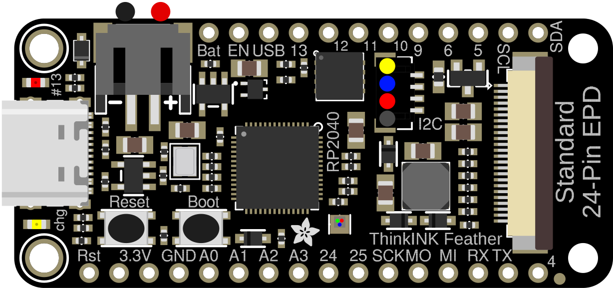
 Design with Adafruit Feather RP2040 ThinkInk in Cirkit Designer
Introduction
The Adafruit Feather RP2040 ThinkInk (Manufacturer Part ID: 5727) is a compact microcontroller board powered by the Raspberry Pi RP2040 chip. It is specifically designed for low-power applications and features an integrated ThinkInk ePaper display for clear, low-energy visual output. This board is part of Adafruit's Feather ecosystem, making it compatible with a wide range of FeatherWing add-ons.
The ThinkInk display is ideal for applications requiring persistent, low-power visual feedback, such as eBook readers, dashboards, or IoT devices. With its dual-core ARM Cortex-M0+ processor, ample GPIO pins, and built-in USB-C connectivity, the Feather RP2040 ThinkInk is a versatile choice for both hobbyists and professionals.
Explore Projects Built with Adafruit Feather RP2040 ThinkInk
 Open Project in Cirkit Designer
 Open Project in Cirkit Designer
 Open Project in Cirkit Designer
 Open Project in Cirkit Designer
Explore Projects Built with Adafruit Feather RP2040 ThinkInk
Open Project in Cirkit DesignerOpen Project in Cirkit DesignerOpen Project in Cirkit DesignerOpen Project in Cirkit DesignerCommon Applications
- Low-power IoT devices with visual feedback
- ePaper-based dashboards and displays
- Portable data loggers
- Wearable electronics
- Educational projects and prototyping
Technical Specifications
Key Technical Details
| Specification | Value |
|---|---|
| Microcontroller | Raspberry Pi RP2040 (Dual-core ARM Cortex-M0+) |
| Clock Speed | 133 MHz |
| Flash Memory | 8 MB (QSPI Flash) |
| RAM | 264 KB SRAM |
| Display | ThinkInk ePaper display (2.13" diagonal) |
| Display Resolution | 250 x 122 pixels |
| Display Colors | Black, White, Red |
| USB Interface | USB-C |
| GPIO Pins | 21 (including I2C, SPI, UART support) |
| Power Supply | 3.3V logic, LiPo battery connector (3.7V) |
| Dimensions | 51mm x 23mm x 8mm |
| Weight | 6.5g |
Pin Configuration and Descriptions
| Pin Number | Pin Name | Description |
|---|---|---|
| 1 | 3V3 | 3.3V power output |
| 2 | GND | Ground |
| 3 | A0 | Analog input 0 |
| 4 | A1 | Analog input 1 |
| 5 | A2 | Analog input 2 |
| 6 | A3 | Analog input 3 |
| 7 | SDA | I2C data line |
| 8 | SCL | I2C clock line |
| 9 | SCK | SPI clock line |
| 10 | MOSI | SPI Master Out Slave In |
| 11 | MISO | SPI Master In Slave Out |
| 12 | RX | UART receive |
| 13 | TX | UART transmit |
| 14 | D5 | Digital GPIO 5 |
| 15 | D6 | Digital GPIO 6 |
| 16 | D9 | Digital GPIO 9 |
| 17 | D10 | Digital GPIO 10 |
| 18 | D11 | Digital GPIO 11 |
| 19 | D12 | Digital GPIO 12 |
| 20 | EN | Enable pin for power control |
| 21 | BAT | LiPo battery voltage input |
Usage Instructions
How to Use the Component in a Circuit
Powering the Board:
- Connect a USB-C cable to power the board via USB.
- Alternatively, connect a 3.7V LiPo battery to the BAT pin for portable applications.
- Ensure the EN pin is connected to enable power to the board.
Connecting Peripherals:
- Use the GPIO pins for connecting sensors, actuators, or other peripherals.
- The board supports I2C, SPI, and UART communication protocols for interfacing with external devices.
Programming the Board:
- The Feather RP2040 ThinkInk can be programmed using CircuitPython, MicroPython, or C/C++ via the Arduino IDE.
- To upload code, connect the board to your computer via USB-C and follow the programming instructions for your chosen environment.
Using the ThinkInk Display:
- The integrated ePaper display can be controlled using Adafruit's
Adafruit_EPDlibrary. - The display supports three colors (black, white, and red) and is ideal for static or low-refresh-rate content.
- The integrated ePaper display can be controlled using Adafruit's
Important Considerations and Best Practices
- Low Power Mode: Use the RP2040's sleep modes to minimize power consumption in battery-powered applications.
- Display Refresh: Avoid frequent updates to the ePaper display, as it is optimized for static content and has a limited refresh rate.
- Voltage Levels: Ensure all connected peripherals operate at 3.3V logic levels to avoid damaging the board.
- Battery Safety: Use only compatible 3.7V LiPo batteries and avoid overcharging or deep discharging.
Example Code for Arduino IDE
Below is an example of how to display text on the ThinkInk ePaper display using the Arduino IDE:
#include <Adafruit_GFX.h>       // Core graphics library
#include <Adafruit_EPD.h>       // Adafruit ePaper display library

// Define display pins
#define EPD_CS    10  // Chip select
#define EPD_DC    9   // Data/command
#define SRAM_CS   6   // SRAM chip select
#define EPD_RESET 5   // Reset pin
#define EPD_BUSY  7   // Busy pin

// Initialize the display
Adafruit_IL0373 display(250, 122, EPD_DC, EPD_RESET, EPD_CS, SRAM_CS, EPD_BUSY);

void setup() {
  // Initialize serial communication
  Serial.begin(115200);
  Serial.println("Initializing ThinkInk display...");

  // Initialize the display
  display.begin();
  display.setRotation(1);  // Set display orientation
  display.fillScreen(EPD_WHITE);  // Clear the screen
  display.setTextColor(EPD_BLACK);  // Set text color
  display.setCursor(10, 10);  // Set text position
  display.setTextSize(2);  // Set text size
  display.print("Hello, ThinkInk!");  // Display text
  display.display();  // Refresh the display
}

void loop() {
  // Nothing to do here
}
Troubleshooting and FAQs
Common Issues and Solutions
The board is not recognized by the computer:
- Ensure the USB-C cable is data-capable (not just for charging).
- Double-tap the reset button to enter bootloader mode and reprogram the board.
The ThinkInk display does not update:
- Verify the display connections and ensure the correct pins are defined in your code.
- Check that the
Adafruit_EPDlibrary is installed and up to date.
The board is not powering on:
- Confirm that the EN pin is connected and not pulled low.
- Check the battery voltage if using a LiPo battery.
The display refresh is slow:
- ePaper displays are inherently slower than LCDs or OLEDs. Optimize your code to minimize unnecessary refreshes.
FAQs
Can I use the board without a battery?
Yes, the board can be powered directly via USB-C without a battery.What is the lifespan of the ThinkInk display?
The display is rated for thousands of refresh cycles, making it suitable for most low-power applications.Is the board compatible with FeatherWings?
Yes, the Feather RP2040 ThinkInk is fully compatible with Adafruit FeatherWing add-ons.
This concludes the documentation for the Adafruit Feather RP2040 ThinkInk. For additional support, visit the Adafruit Learning System.