
How to Use STM32F103C8T6 blue mini board: Examples, Pinouts, and Specs

 Design with STM32F103C8T6 blue mini board in Cirkit Designer
Introduction
The STM32F103C8T6 Blue Mini Board is a compact development board built around the STM32F103C8T6 microcontroller, which is based on the ARM Cortex-M3 architecture. This board is widely used in embedded systems development due to its powerful processing capabilities, low power consumption, and versatile I/O options. It features USB connectivity, making it easy to program and communicate with other devices.
Explore Projects Built with STM32F103C8T6 blue mini board
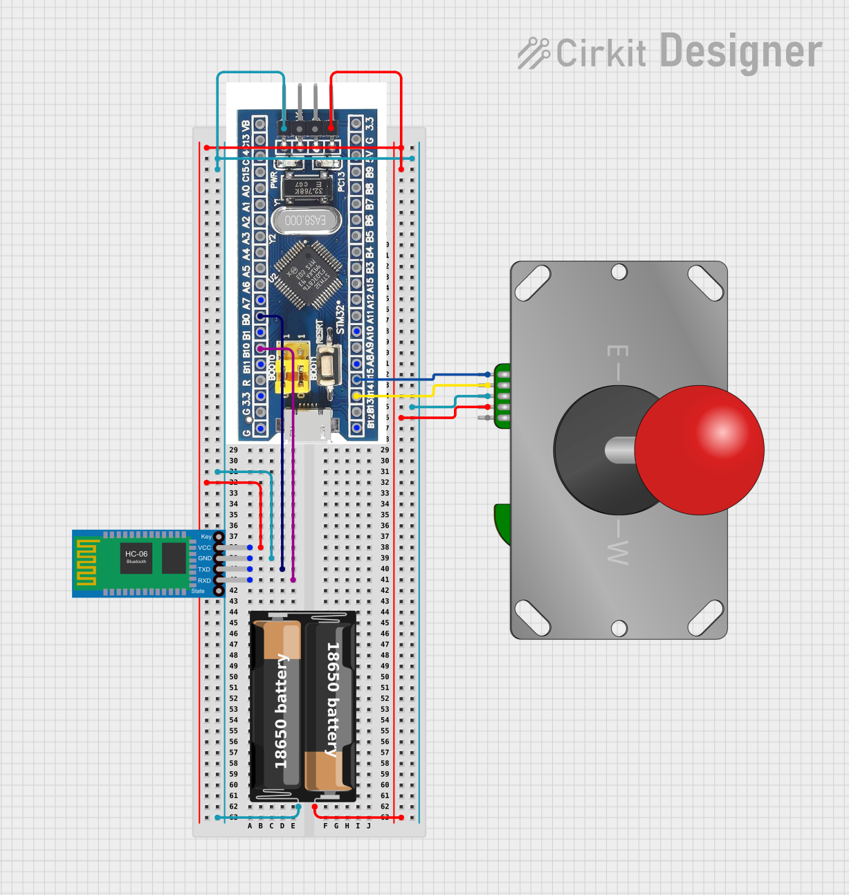 Open Project in Cirkit Designer
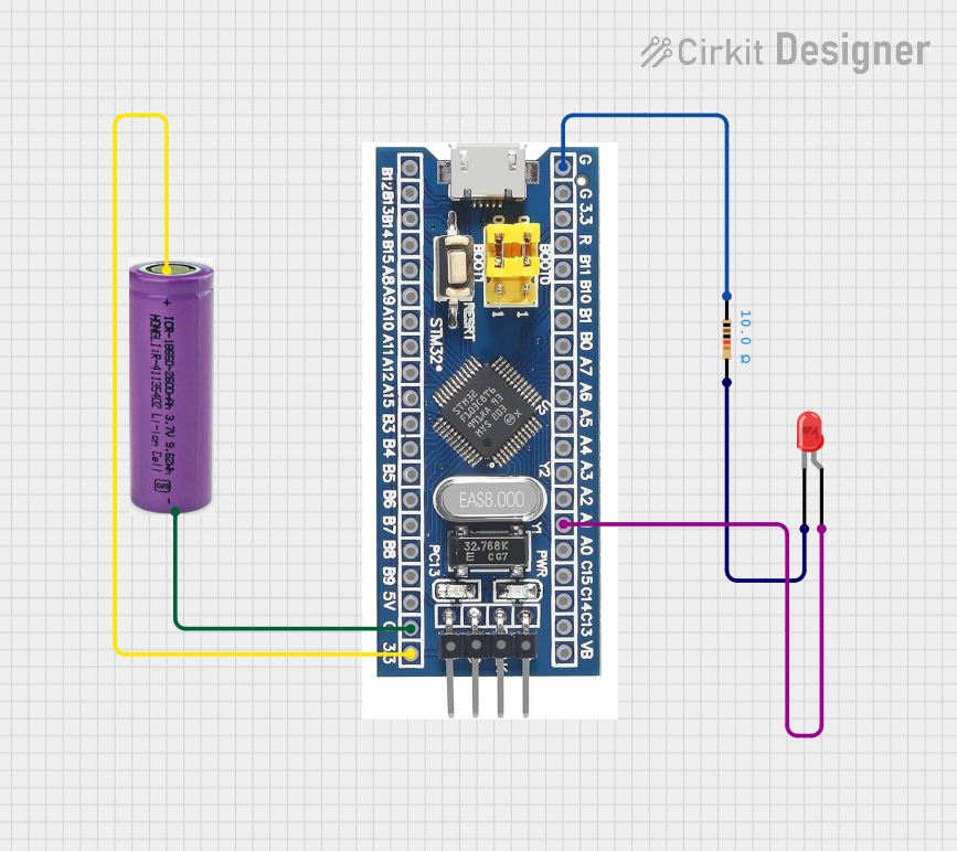 Open Project in Cirkit Designer
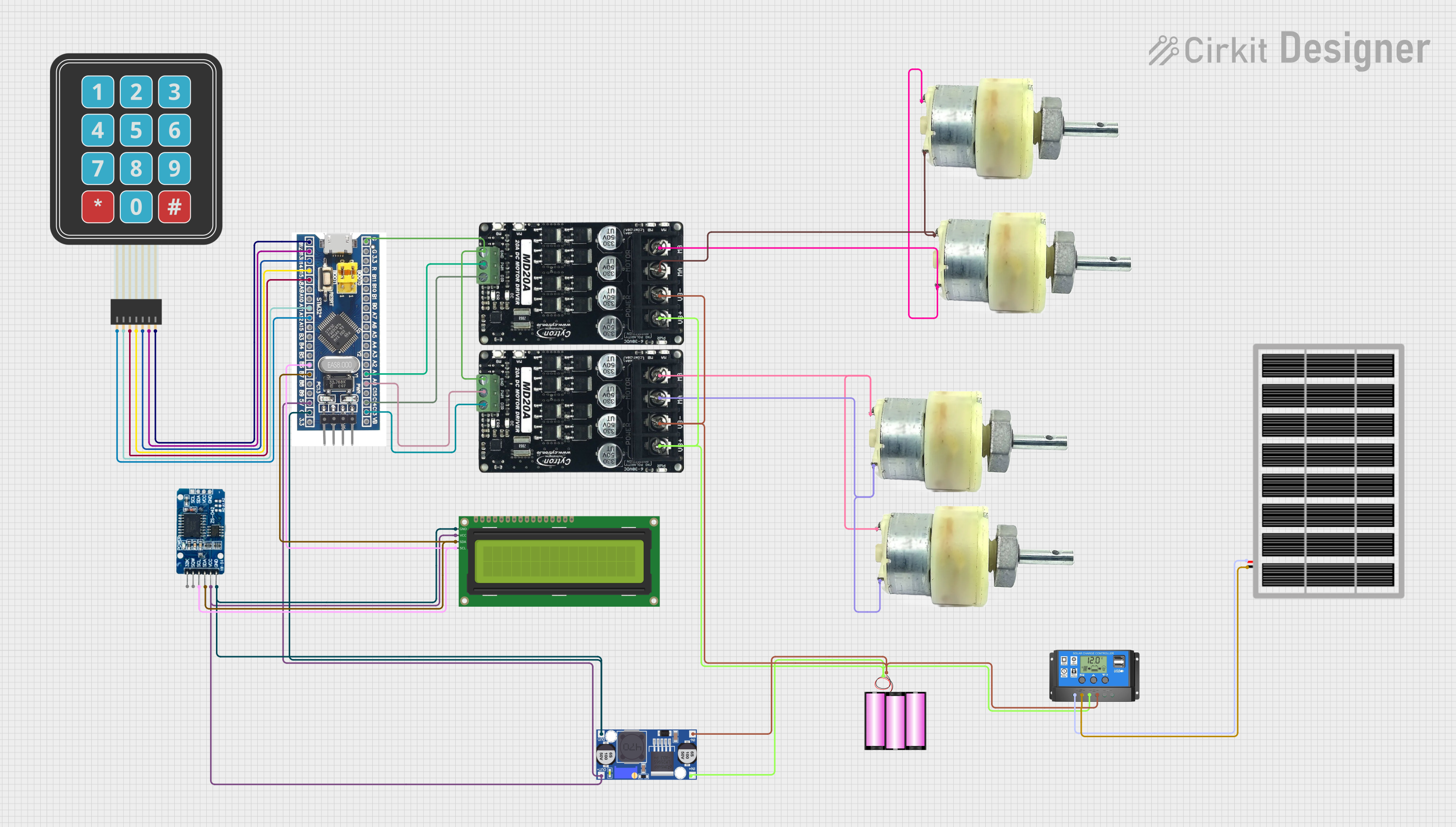 Open Project in Cirkit Designer
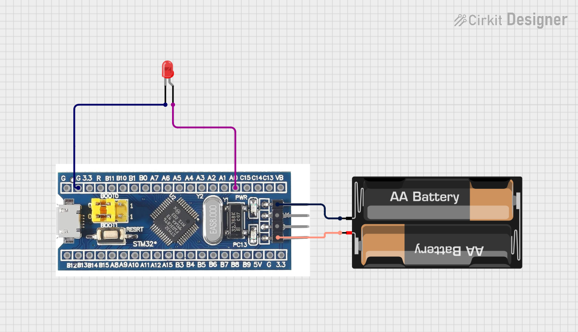 Open Project in Cirkit Designer
Explore Projects Built with STM32F103C8T6 blue mini board
Open Project in Cirkit DesignerOpen Project in Cirkit DesignerOpen Project in Cirkit DesignerOpen Project in Cirkit DesignerCommon Applications and Use Cases
- Prototyping embedded systems
- IoT (Internet of Things) devices
- Robotics and motor control
- Data acquisition systems
- Home automation projects
- Educational purposes for learning ARM Cortex-M3 programming
Technical Specifications
The STM32F103C8T6 Blue Mini Board offers the following key technical details:
Microcontroller Specifications
- Microcontroller: STM32F103C8T6
- Core: ARM Cortex-M3, 32-bit
- Operating Frequency: 72 MHz
- Flash Memory: 64 KB
- SRAM: 20 KB
- Operating Voltage: 2.0V to 3.6V
- I/O Pins: 37 GPIOs
- Communication Interfaces: USART, SPI, I2C, CAN, USB
- ADC: 12-bit, up to 16 channels
- Timers: 7 (including advanced control timers)
Pin Configuration and Descriptions
The STM32F103C8T6 Blue Mini Board has a 40-pin layout. Below is the pin configuration:
| Pin | Label | Description |
|---|---|---|
| 1 | 3.3V | 3.3V Power Output |
| 2 | GND | Ground |
| 3 | PA0 | GPIO/ADC Channel 0 |
| 4 | PA1 | GPIO/ADC Channel 1 |
| 5 | PA2 | GPIO/USART2_TX |
| 6 | PA3 | GPIO/USART2_RX |
| 7 | PA4 | GPIO/SPI1_NSS/ADC Channel 4 |
| 8 | PA5 | GPIO/SPI1_SCK/ADC Channel 5 |
| 9 | PA6 | GPIO/SPI1_MISO/ADC Channel 6 |
| 10 | PA7 | GPIO/SPI1_MOSI/ADC Channel 7 |
| ... | ... | ... (other pins follow similar format) |
For the complete pinout, refer to the STM32F103C8T6 datasheet.
Usage Instructions
How to Use the STM32F103C8T6 Blue Mini Board in a Circuit
Powering the Board:
- The board can be powered via the USB port or through the 5V and GND pins.
- Ensure the input voltage does not exceed the recommended range (2.0V to 3.6V for the microcontroller).
Programming the Board:
- Use a USB-to-Serial adapter or an ST-Link programmer to upload code.
- Popular IDEs for programming include STM32CubeIDE, Keil uVision, and PlatformIO.
Connecting Peripherals:
- Use the GPIO pins for interfacing with sensors, actuators, and other devices.
- Communication protocols like I2C, SPI, and UART are available for connecting external modules.
Using the USB Port:
- The USB port can be used for programming or as a communication interface (e.g., USB CDC).
Important Considerations and Best Practices
- Always check the pinout to avoid incorrect connections that could damage the board.
- Use decoupling capacitors near power pins to ensure stable operation.
- Avoid exceeding the maximum current rating of the GPIO pins (25 mA per pin).
- Use pull-up or pull-down resistors for unused pins to prevent floating states.
Example Code for Arduino IDE
The STM32F103C8T6 Blue Mini Board can be programmed using the Arduino IDE with the STM32duino core installed. Below is an example of blinking an LED connected to pin PA5:
// Include the Arduino core for STM32
#include <Arduino.h>

// Define the LED pin (PA5 is connected to the onboard LED)
#define LED_PIN PA5

void setup() {
  pinMode(LED_PIN, OUTPUT); // Set PA5 as an output pin
}

void loop() {
  digitalWrite(LED_PIN, HIGH); // Turn the LED on
  delay(500);                  // Wait for 500 milliseconds
  digitalWrite(LED_PIN, LOW);  // Turn the LED off
  delay(500);                  // Wait for 500 milliseconds
}
Troubleshooting and FAQs
Common Issues and Solutions
The board is not detected by the computer:
- Ensure the USB cable is functional and supports data transfer.
- Check if the correct drivers for the STM32 are installed on your computer.
Unable to upload code:
- Verify that the board is in programming mode (BOOT0 pin set to 1).
- Ensure the correct COM port is selected in the IDE.
The board is not powering on:
- Check the power supply voltage and connections.
- Inspect the board for any visible damage or loose components.
GPIO pins are not functioning as expected:
- Confirm the pin mode is correctly configured in the code.
- Check for short circuits or incorrect wiring.
FAQs
Q: Can I use the STM32F103C8T6 Blue Mini Board with 5V logic devices?
A: The board operates at 3.3V logic levels. Use level shifters to interface with 5V devices.
Q: What is the maximum clock speed of the STM32F103C8T6?
A: The maximum clock speed is 72 MHz.
Q: Can I use the Arduino IDE to program this board?
A: Yes, with the STM32duino core installed, the Arduino IDE can be used to program the board.
Q: How do I reset the board?
A: Press the onboard reset button or toggle the NRST pin.
By following this documentation, users can effectively utilize the STM32F103C8T6 Blue Mini Board for a variety of embedded applications.