How to Use 5V step up/doown: Examples, Pinouts, and Specs
Introduction
The 5V Step Up/Down is a DC-DC converter designed to regulate a 5V input voltage by either increasing (stepping up) or decreasing (stepping down) it to a desired output voltage. This versatile component is ideal for applications requiring a stable voltage supply, regardless of fluctuations in the input voltage. It is commonly used in battery-powered devices, portable electronics, and projects requiring efficient power management.
Explore Projects Built with 5V step up/doown


Explore Projects Built with 5V step up/doown
Common Applications
- Powering microcontrollers and sensors in embedded systems
- Battery-powered devices with varying input voltage
- Portable electronics requiring a stable voltage supply
- Robotics and IoT devices
- LED drivers and small motor controllers
Technical Specifications
The following table outlines the key technical details of the 5V Step Up/Down converter:
| Parameter | Value |
|---|---|
| Input Voltage Range | 2V to 24V |
| Output Voltage Range | 1.8V to 24V (adjustable via potentiometer) |
| Output Current | Up to 2A (depending on input/output voltage) |
| Efficiency | Up to 90% (varies with load and voltage) |
| Switching Frequency | 150 kHz |
| Operating Temperature | -40°C to +85°C |
| Dimensions | Typically 22mm x 17mm x 4mm |
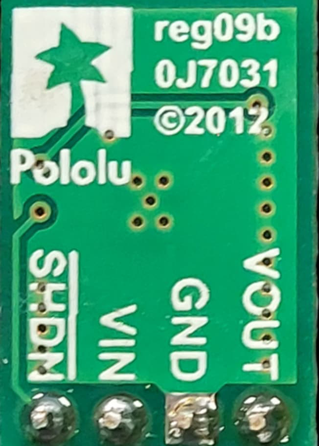
Pin Configuration and Descriptions
The 5V Step Up/Down module typically has the following pinout:
| Pin Name | Description |
|---|---|
| VIN | Input voltage (connect to power source) |
| GND | Ground (common ground for input and output) |
| VOUT | Regulated output voltage (connect to load) |
| ADJ | Adjustment pin (used to set the output voltage) |
Usage Instructions
How to Use the Component in a Circuit
Connect the Input Voltage:
- Connect the VIN pin to your power source (e.g., a battery or power supply).
- Ensure the input voltage is within the specified range (2V to 24V).
Connect the Ground:
- Connect the GND pin to the ground of your circuit.
Set the Output Voltage:
- Use a small screwdriver to adjust the onboard potentiometer (connected to the ADJ pin).
- Measure the output voltage at the VOUT pin using a multimeter while adjusting the potentiometer.
Connect the Load:
- Connect your load (e.g., microcontroller, sensor, or motor) to the VOUT pin.
- Ensure the load does not exceed the maximum output current rating (2A).
Important Considerations and Best Practices
- Heat Dissipation: If the module is operating at high currents, ensure proper ventilation or add a heatsink to prevent overheating.
- Input Voltage: Always ensure the input voltage is within the specified range to avoid damaging the module.
- Output Voltage Adjustment: Adjust the potentiometer slowly and carefully to avoid overshooting the desired voltage.
- Capacitor Placement: For improved stability, consider adding external capacitors (e.g., 10µF) near the input and output pins.
Example: Using with an Arduino UNO
The 5V Step Up/Down can be used to power an Arduino UNO from a battery. Below is an example circuit and code:
Circuit Connections
- Connect the VIN pin to the positive terminal of a 3.7V Li-ion battery.
- Connect the GND pin to the battery's negative terminal and the Arduino's GND.
- Adjust the output voltage to 5V using the potentiometer.
- Connect the VOUT pin to the Arduino's 5V pin.
Arduino Code Example
// Example code to blink an LED using an Arduino UNO powered by the 5V Step Up/Down
// Ensure the output voltage of the module is set to 5V before connecting to the Arduino.

const int ledPin = 13; // Pin connected to the onboard LED

void setup() {
  pinMode(ledPin, OUTPUT); // Set the LED pin as an output
}

void loop() {
  digitalWrite(ledPin, HIGH); // Turn the LED on
  delay(1000);                // Wait for 1 second
  digitalWrite(ledPin, LOW);  // Turn the LED off
  delay(1000);                // Wait for 1 second
}
Troubleshooting and FAQs
Common Issues and Solutions
No Output Voltage:
- Check the input voltage and ensure it is within the specified range.
- Verify all connections are secure and correct.
- Ensure the potentiometer is not set to an extremely low or high value.
Overheating:
- Reduce the load current if it exceeds the module's capacity.
- Improve ventilation or add a heatsink to the module.
Unstable Output Voltage:
- Add external capacitors (e.g., 10µF or 100µF) near the input and output pins.
- Ensure the input voltage is stable and not fluctuating.
Output Voltage Not Adjustable:
- Verify the potentiometer is functioning correctly.
- Check for any physical damage to the module.
FAQs
Q: Can this module step up and step down simultaneously?
A: Yes, the module automatically adjusts to step up or step down the input voltage to maintain the desired output voltage.
Q: What happens if the input voltage exceeds 24V?
A: Exceeding the input voltage range can damage the module. Always ensure the input voltage is within the specified range.
Q: Can I use this module to power a Raspberry Pi?
A: Yes, but ensure the output voltage is set to 5V and the current requirement of the Raspberry Pi is within the module's capacity.
Q: Is the module suitable for audio applications?
A: While it can be used, the switching frequency (150 kHz) may introduce noise in sensitive audio circuits. Use additional filtering if needed.