Cirkit Designer Logo
Cirkit Designer
Your all-in-one circuit design IDE
Home / 
Component Documentation

How to Use FS1000A 433MHz RF Transmitter: Examples, Pinouts, and Specs

Image of FS1000A 433MHz RF Transmitter
Cirkit Designer LogoDesign with FS1000A 433MHz RF Transmitter in Cirkit Designer

Introduction

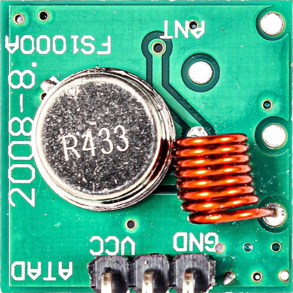
The FS1000A 433MHz RF Transmitter is a low-cost, compact wireless module capable of transmitting radio signals at the frequency of 433MHz. It is widely used in various applications such as remote controls, wireless alarm systems, home automation, and telemetry. Due to its ease of use and ability to interface with microcontrollers like the Arduino UNO, it has become a popular choice for hobbyists and professionals alike.

Explore Projects Built with FS1000A 433MHz RF Transmitter

Use Cirkit Designer to design, explore, and prototype these projects online. Some projects support real-time simulation. Click "Open Project" to start designing instantly!
433 MHz RF Transmitter and Receiver with Arduino UNO for Wireless Communication
Image of Wireless Communication: A project utilizing FS1000A 433MHz RF Transmitter in a practical application
This circuit consists of two Arduino UNO microcontrollers, each connected to an RF 433 MHz Transmitter and a 433 MHz RF Receiver Module. The setup allows for wireless communication between the two Arduinos, enabling them to send and receive data over a 433 MHz RF link.
Cirkit Designer LogoOpen Project in Cirkit Designer
ESP32-Based RF Communication System with 433 MHz Modules
Image of 433 mhz: A project utilizing FS1000A 433MHz RF Transmitter in a practical application
This circuit comprises an ESP32 microcontroller connected to a 433 MHz RF transmitter and receiver pair. The ESP32 is programmed to receive and decode RF signals through the receiver module, as well as send RF signals via the transmitter module. Additionally, the ESP32 can communicate with a Bluetooth device to exchange commands and data, and it uses an LED for status indication.
Cirkit Designer LogoOpen Project in Cirkit Designer
433 MHz RF Transmitter and Receiver with Arduino Uno for Wireless LED Control
Image of rf module up: A project utilizing FS1000A 433MHz RF Transmitter in a practical application
This circuit consists of two Arduino Uno R3 microcontrollers communicating wirelessly using 433 MHz RF modules. One Arduino is connected to an RF transmitter to send data, while the other Arduino is connected to an RF receiver to receive data and control an LED based on the received signal.
Cirkit Designer LogoOpen Project in Cirkit Designer
Arduino-Based RF-Controlled MOSFET Switch with Battery Power
Image of radio shit: A project utilizing FS1000A 433MHz RF Transmitter in a practical application
This circuit consists of two Arduino UNOs communicating wirelessly using 433MHz RF modules. One Arduino sends 'yes' or 'no' signals via an RF transmitter, while the other Arduino receives these signals through an RF receiver and controls a MOSFET to switch a 12V power source on or off based on the received signal.
Cirkit Designer LogoOpen Project in Cirkit Designer

Explore Projects Built with FS1000A 433MHz RF Transmitter

Use Cirkit Designer to design, explore, and prototype these projects online. Some projects support real-time simulation. Click "Open Project" to start designing instantly!
Image of Wireless Communication: A project utilizing FS1000A 433MHz RF Transmitter in a practical application
433 MHz RF Transmitter and Receiver with Arduino UNO for Wireless Communication
This circuit consists of two Arduino UNO microcontrollers, each connected to an RF 433 MHz Transmitter and a 433 MHz RF Receiver Module. The setup allows for wireless communication between the two Arduinos, enabling them to send and receive data over a 433 MHz RF link.
Cirkit Designer LogoOpen Project in Cirkit Designer
Image of 433 mhz: A project utilizing FS1000A 433MHz RF Transmitter in a practical application
ESP32-Based RF Communication System with 433 MHz Modules
This circuit comprises an ESP32 microcontroller connected to a 433 MHz RF transmitter and receiver pair. The ESP32 is programmed to receive and decode RF signals through the receiver module, as well as send RF signals via the transmitter module. Additionally, the ESP32 can communicate with a Bluetooth device to exchange commands and data, and it uses an LED for status indication.
Cirkit Designer LogoOpen Project in Cirkit Designer
Image of rf module up: A project utilizing FS1000A 433MHz RF Transmitter in a practical application
433 MHz RF Transmitter and Receiver with Arduino Uno for Wireless LED Control
This circuit consists of two Arduino Uno R3 microcontrollers communicating wirelessly using 433 MHz RF modules. One Arduino is connected to an RF transmitter to send data, while the other Arduino is connected to an RF receiver to receive data and control an LED based on the received signal.
Cirkit Designer LogoOpen Project in Cirkit Designer
Image of radio shit: A project utilizing FS1000A 433MHz RF Transmitter in a practical application
Arduino-Based RF-Controlled MOSFET Switch with Battery Power
This circuit consists of two Arduino UNOs communicating wirelessly using 433MHz RF modules. One Arduino sends 'yes' or 'no' signals via an RF transmitter, while the other Arduino receives these signals through an RF receiver and controls a MOSFET to switch a 12V power source on or off based on the received signal.
Cirkit Designer LogoOpen Project in Cirkit Designer

Technical Specifications

Key Technical Details

  • Frequency: 433MHz
  • Voltage: 3V to 12V (Vcc)
  • Current Consumption: 9mA (typical at 3V)
  • Modulation: Amplitude Shift Keying (ASK)
  • Transmission Range: 20-200 meters (environment dependent)
  • Operating Temperature: -10°C to +70°C

Pin Configuration and Descriptions

Pin Number Name Description
1 Vcc Power supply (3V to 12V)
2 Data Data input from microcontroller
3 GND Ground connection

Usage Instructions

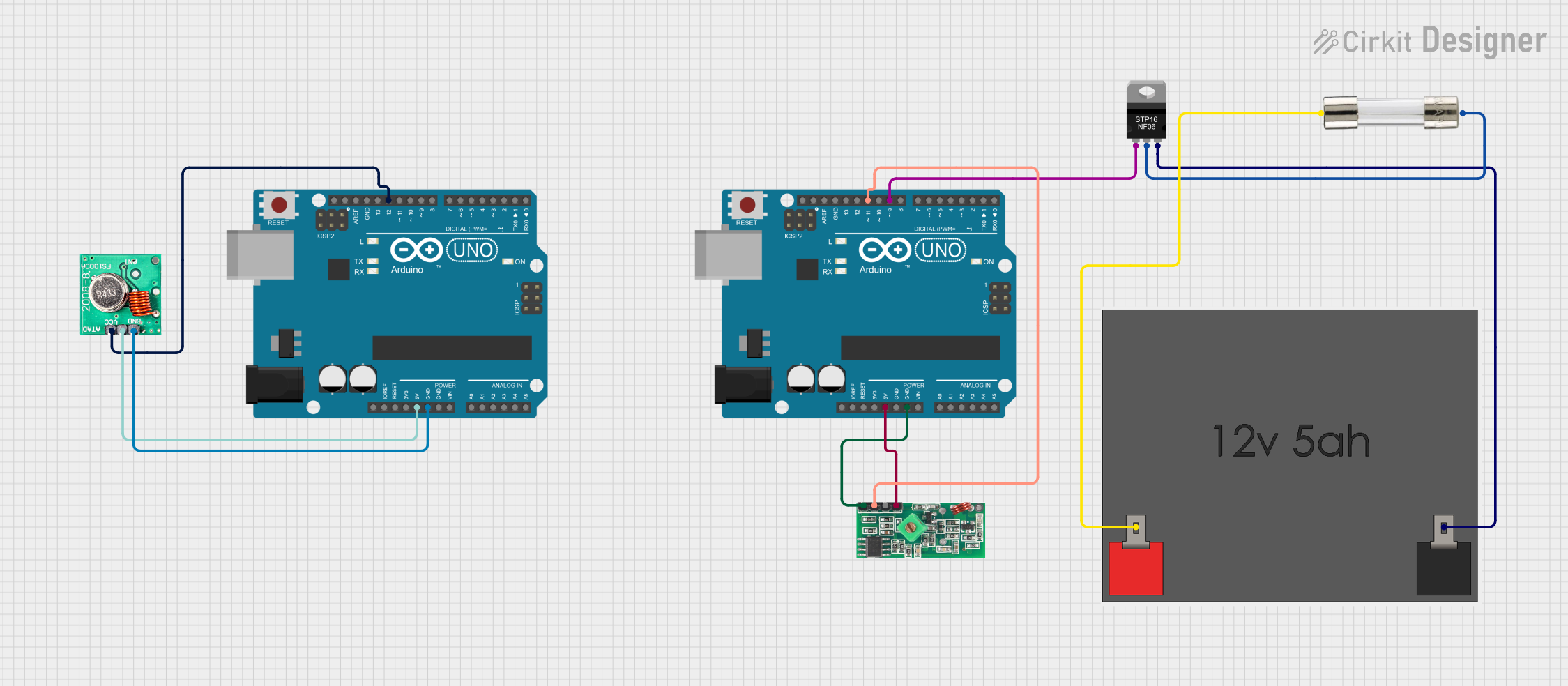
Interfacing with a Circuit

  1. Power Supply: Connect the Vcc pin to a 3V to 12V power source. Ensure that the power supply is clean and stable.
  2. Data Input: The Data pin should be connected to a digital output pin on the microcontroller.
  3. Ground: Connect the GND pin to the ground of the power supply and the microcontroller.

Important Considerations and Best Practices

  • Antenna: For optimal range, attach a 17cm wire to the antenna pad or the module to act as an antenna.
  • Power Supply: Avoid power supply noise as it can affect the transmission quality. A decoupling capacitor (e.g., 10uF) between Vcc and GND can help.
  • Data Rate: Keep the data rate below 10kbps to ensure reliable communication.
  • Pairing: Ensure that the transmitter and receiver are tuned to the same frequency for proper communication.

Example Code for Arduino UNO

#include <VirtualWire.h>

const int transmit_pin = 12; // FS1000A Data pin connected to Arduino pin 12

void setup() {
    vw_set_tx_pin(transmit_pin); // Set the transmit pin
    vw_setup(2000); // Bits per sec
}

void loop() {
    const char *msg = "hello";
    
    vw_send((uint8_t *)msg, strlen(msg)); // Send the message
    vw_wait_tx(); // Wait until the whole message is gone
    delay(1000); // Wait for a second before sending the next message
}

Troubleshooting and FAQs

Common Issues

  • No Signal: Ensure the antenna is properly attached and the power supply is within the specified range.
  • Weak Signal: Increase the power supply voltage up to 12V for a stronger signal or check the antenna length.
  • Interference: Use a different channel or frequency if there is significant interference from other devices.

Solutions and Tips

  • Antenna Length: Use a quarter wavelength antenna for 433MHz, which is approximately 17cm.
  • Power Supply: Always use a regulated power supply and consider using a decoupling capacitor.
  • Pairing: Make sure the receiver module is compatible with the FS1000A and is set to the same frequency.

FAQs

Q: Can I use multiple FS1000A modules together? A: Yes, but ensure each transmitter-receiver pair operates on a different frequency or use time-division multiplexing to avoid interference.

Q: What is the maximum range I can achieve with the FS1000A? A: The range is highly dependent on the environment, antenna, and power supply, but under optimal conditions, it can reach up to 200 meters.

Q: How can I increase the transmission range? A: Use the maximum rated voltage for Vcc, ensure a clear line of sight, and use a proper antenna.

Q: Is the FS1000A compatible with all microcontrollers? A: The FS1000A can be interfaced with any microcontroller that has a digital output pin, including Arduino, Raspberry Pi, and ESP8266.

For further assistance, consult the community forums or the manufacturer's technical support.