How to Use RELAY HD: Examples, Pinouts, and Specs
Introduction
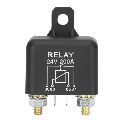
The RELAY HD, manufactured by CAR (Part ID: CAR), is a high-density relay designed for switching electrical circuits. It is capable of handling high current loads while providing electrical isolation between the control and load circuits. This makes it an essential component in applications requiring reliable and efficient switching.
Explore Projects Built with RELAY HD

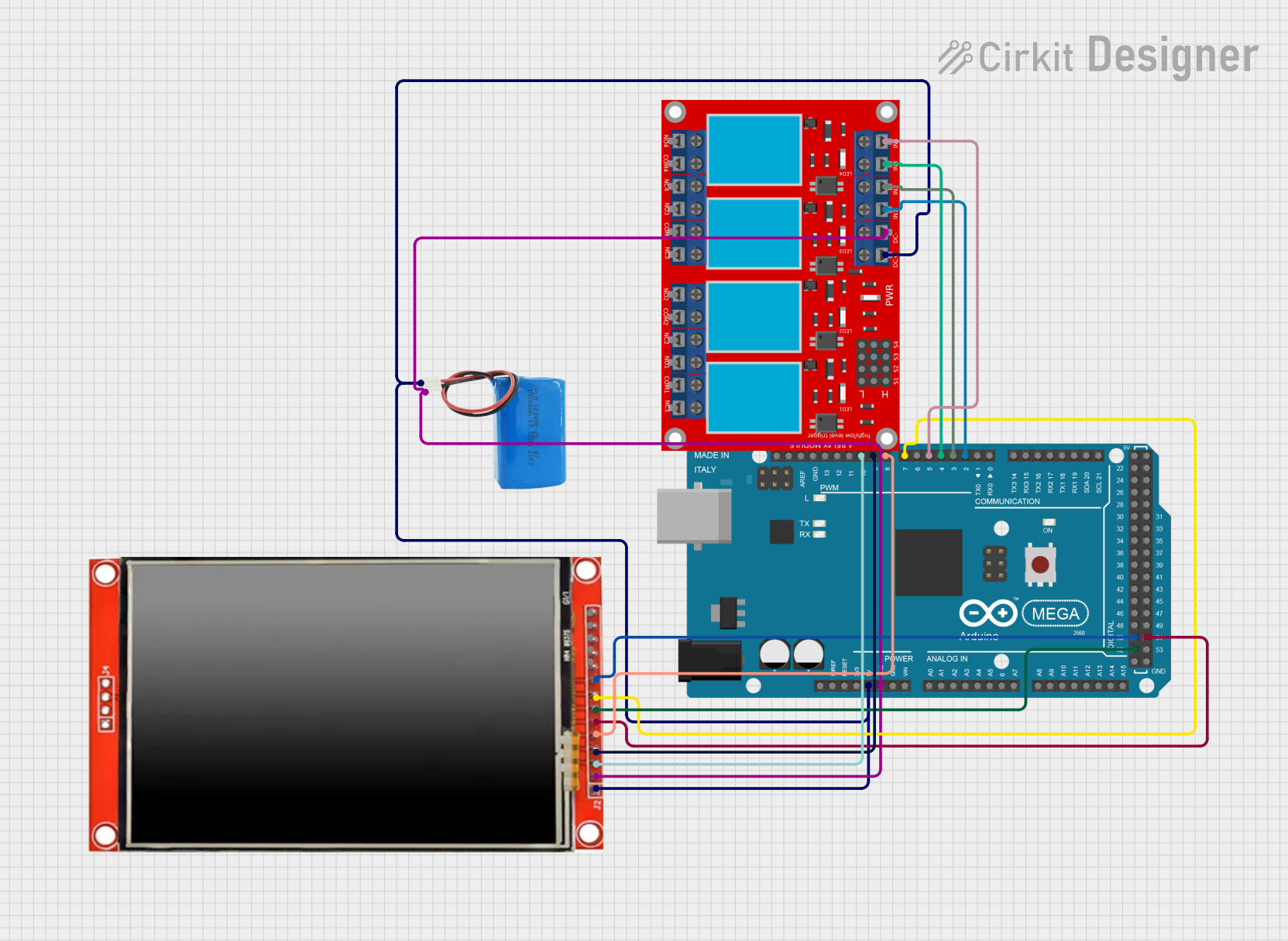

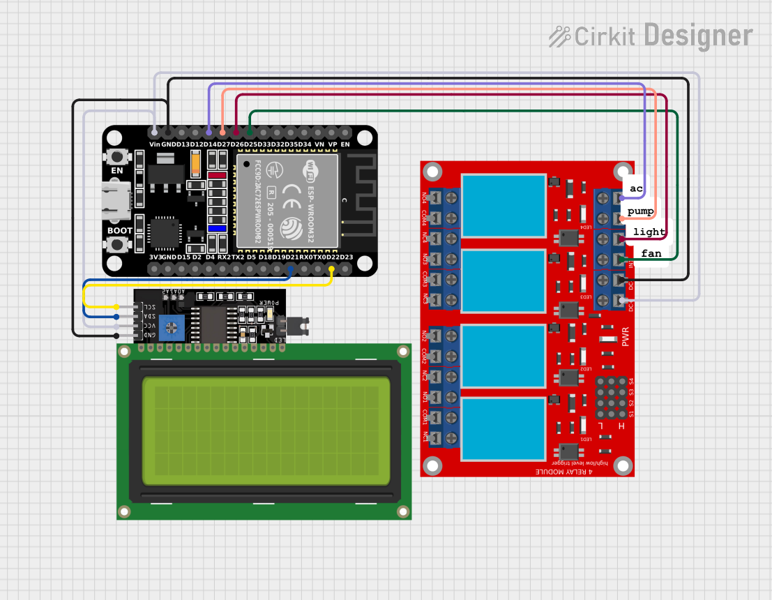
Explore Projects Built with RELAY HD
Common Applications and Use Cases
- Home Automation: Controlling appliances such as lights, fans, and HVAC systems.
- Industrial Automation: Switching high-power machinery and equipment.
- Automotive Systems: Managing electrical loads in vehicles.
- Power Distribution: Isolating and switching power circuits in distribution systems.
- Microcontroller Projects: Interfacing with low-power control systems like Arduino or Raspberry Pi.
Technical Specifications
The following table outlines the key technical details of the RELAY HD:
| Parameter | Value |
|---|---|
| Manufacturer | CAR |
| Part ID | CAR |
| Operating Voltage | 5V DC (control side) |
| Switching Voltage | Up to 250V AC / 30V DC |
| Maximum Current Load | 10A |
| Contact Type | SPDT (Single Pole Double Throw) |
| Coil Resistance | 70Ω |
| Isolation Voltage | 1500V AC |
| Operating Temperature | -40°C to +85°C |
| Dimensions | 29mm x 12.7mm x 15mm |
Pin Configuration and Descriptions
The RELAY HD has a standard 5-pin configuration. The table below describes each pin:
| Pin Number | Name | Description |
|---|---|---|
| 1 | Coil+ (VCC) | Positive terminal of the relay coil. Connect to the control voltage (e.g., 5V). |
| 2 | Coil- (GND) | Negative terminal of the relay coil. Connect to ground. |
| 3 | Common (COM) | Common terminal for the load circuit. |
| 4 | Normally Open (NO) | Open when the relay is inactive; closes when the relay is activated. |
| 5 | Normally Closed (NC) | Closed when the relay is inactive; opens when the relay is activated. |
Usage Instructions
How to Use the RELAY HD in a Circuit
- Power the Relay Coil: Connect the
Coil+pin to a 5V DC power source and theCoil-pin to ground. This energizes the relay coil. - Connect the Load Circuit:
- Attach the load's input to the
COMpin. - Use the
NOpin if you want the load to be powered only when the relay is activated. - Use the
NCpin if you want the load to be powered when the relay is inactive.
- Attach the load's input to the
- Control the Relay: Use a microcontroller or a switch to control the relay coil. When the coil is energized, the relay switches from NC to NO.
Important Considerations and Best Practices
- Diode Protection: Always connect a flyback diode across the relay coil to protect the control circuit from voltage spikes when the relay is de-energized.
- Current Ratings: Ensure the load current does not exceed the relay's maximum current rating of 10A.
- Isolation: Use the relay to isolate high-voltage circuits from low-voltage control systems.
- Mounting: Secure the relay properly to avoid mechanical vibrations that could affect performance.
Example: Using RELAY HD with Arduino UNO
Below is an example of how to control the RELAY HD using an Arduino UNO:
// Define the pin connected to the relay control
const int relayPin = 7;

void setup() {
  pinMode(relayPin, OUTPUT); // Set the relay pin as an output
  digitalWrite(relayPin, LOW); // Ensure the relay is off initially
}

void loop() {
  digitalWrite(relayPin, HIGH); // Activate the relay
  delay(1000); // Keep the relay on for 1 second
  digitalWrite(relayPin, LOW); // Deactivate the relay
  delay(1000); // Keep the relay off for 1 second
}
Note: Ensure the relay is connected to the Arduino through a transistor or relay driver circuit, as the Arduino's GPIO pins cannot supply sufficient current to directly drive the relay.
Troubleshooting and FAQs
Common Issues and Solutions
Relay Not Switching:
- Cause: Insufficient voltage or current to the relay coil.
- Solution: Verify the control voltage is 5V and the power supply can provide adequate current.
Load Not Powering On:
- Cause: Incorrect wiring of the load circuit.
- Solution: Double-check the connections to the
COM,NO, andNCpins.
Excessive Heat:
- Cause: Overloading the relay beyond its current rating.
- Solution: Ensure the load current does not exceed 10A.
Noise or Chattering:
- Cause: Unstable control voltage or mechanical vibrations.
- Solution: Use a stable power supply and secure the relay in place.
FAQs
Q: Can the RELAY HD handle DC loads?
- A: Yes, it can switch DC loads up to 30V at 10A.
Q: Is the RELAY HD suitable for high-frequency switching?
- A: No, relays are not ideal for high-frequency applications due to mechanical limitations.
Q: Can I use the RELAY HD with a 3.3V control signal?
- A: No, the relay requires a 5V control signal. Use a level shifter or transistor circuit to interface with 3.3V systems.
Q: Does the RELAY HD require a heatsink?
- A: No, as long as the load current is within the specified limit, no additional cooling is required.