Cirkit Designer Logo
Cirkit Designer
Your all-in-one circuit design IDE
Home / 
Component Documentation

How to Use Teensy ELS Keypad: Examples, Pinouts, and Specs

Image of Teensy ELS Keypad
Cirkit Designer LogoDesign with Teensy ELS Keypad in Cirkit Designer

Introduction

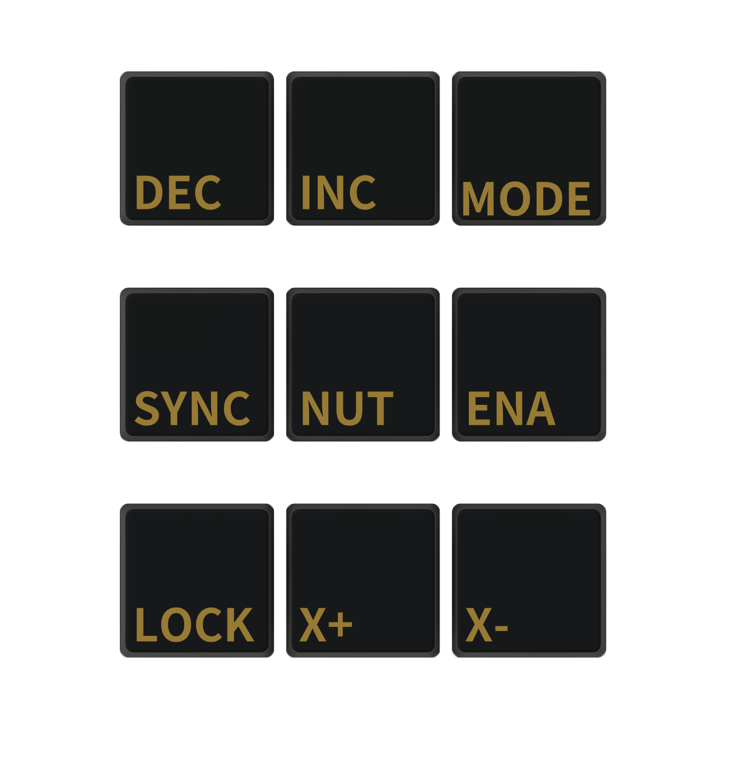
The Teensy ELS Keypad is a versatile and customizable input device based on the powerful Teensy development board platform. It is designed to offer a tactile interface for electronic projects, allowing users to input commands, control systems, or navigate menus. The keypad is often utilized in DIY electronics, interactive installations, and prototypes that require user interaction.

Explore Projects Built with Teensy ELS Keypad

Use Cirkit Designer to design, explore, and prototype these projects online. Some projects support real-time simulation. Click "Open Project" to start designing instantly!
ESP32-Based Interactive Keypad with TFT Display and Audio Output
Image of banking: A project utilizing Teensy ELS Keypad in a practical application
This circuit features an ESP32 microcontroller interfaced with a 4x4 membrane matrix keypad, an ILI9341 TFT display, a DFPlayer Mini MP3 player, and a loudspeaker. The ESP32 reads input from the keypad, controls the display, and communicates with the DFPlayer Mini to play audio through the loudspeaker.
Cirkit Designer LogoOpen Project in Cirkit Designer
Teensy 4.1 Controlled Precision Stepper Motor System with OLED Display and Logic Level Conversion
Image of Teensy ELS V2.2: A project utilizing Teensy ELS Keypad in a practical application
This circuit features a Teensy 4.1 microcontroller interfaced with a keypad for user input, an OLED display for visual feedback, and an optical rotary encoder for position sensing. It controls a closed-loop stepper motor via a Stepperonline CL57T driver, with a bi-directional logic level converter to ensure compatible voltage levels between the microcontroller and the stepper driver. The circuit is likely designed for precise motion control applications, such as CNC machines or robotic systems, where user input is used to adjust parameters like pitch or position.
Cirkit Designer LogoOpen Project in Cirkit Designer
ESP32-Based Wi-Fi Controlled LED and Keypad Interface with LCD Display
Image of NINA EXPIRY DATE: A project utilizing Teensy ELS Keypad in a practical application
This circuit features two ESP32 microcontrollers interfaced with various components including a 4x4 membrane keypad, multiple LEDs, a piezo buzzer, and an LCD display. The ESP32 microcontrollers control the LEDs and read inputs from the keypad, while the AMS1117 voltage regulators ensure stable 3.3V power supply. A bi-directional logic level converter is used to interface the ESP32 with the 5V LCD display.
Cirkit Designer LogoOpen Project in Cirkit Designer
Arduino UNO Keypad-Controlled LED and Buzzer System with RTC and Bluetooth
Image of Uni: A project utilizing Teensy ELS Keypad in a practical application
This circuit is an Arduino-based keypad interface system that reads input from a 4x4 membrane matrix keypad and displays the pressed key on the serial monitor. It also includes a real-time clock (RTC) module, a Bluetooth module, and visual indicators using red and green LEDs. Additionally, a buzzer is controlled via an NPN transistor for audio feedback.
Cirkit Designer LogoOpen Project in Cirkit Designer

Explore Projects Built with Teensy ELS Keypad

Use Cirkit Designer to design, explore, and prototype these projects online. Some projects support real-time simulation. Click "Open Project" to start designing instantly!
Image of banking: A project utilizing Teensy ELS Keypad in a practical application
ESP32-Based Interactive Keypad with TFT Display and Audio Output
This circuit features an ESP32 microcontroller interfaced with a 4x4 membrane matrix keypad, an ILI9341 TFT display, a DFPlayer Mini MP3 player, and a loudspeaker. The ESP32 reads input from the keypad, controls the display, and communicates with the DFPlayer Mini to play audio through the loudspeaker.
Cirkit Designer LogoOpen Project in Cirkit Designer
Image of Teensy ELS V2.2: A project utilizing Teensy ELS Keypad in a practical application
Teensy 4.1 Controlled Precision Stepper Motor System with OLED Display and Logic Level Conversion
This circuit features a Teensy 4.1 microcontroller interfaced with a keypad for user input, an OLED display for visual feedback, and an optical rotary encoder for position sensing. It controls a closed-loop stepper motor via a Stepperonline CL57T driver, with a bi-directional logic level converter to ensure compatible voltage levels between the microcontroller and the stepper driver. The circuit is likely designed for precise motion control applications, such as CNC machines or robotic systems, where user input is used to adjust parameters like pitch or position.
Cirkit Designer LogoOpen Project in Cirkit Designer
Image of NINA EXPIRY DATE: A project utilizing Teensy ELS Keypad in a practical application
ESP32-Based Wi-Fi Controlled LED and Keypad Interface with LCD Display
This circuit features two ESP32 microcontrollers interfaced with various components including a 4x4 membrane keypad, multiple LEDs, a piezo buzzer, and an LCD display. The ESP32 microcontrollers control the LEDs and read inputs from the keypad, while the AMS1117 voltage regulators ensure stable 3.3V power supply. A bi-directional logic level converter is used to interface the ESP32 with the 5V LCD display.
Cirkit Designer LogoOpen Project in Cirkit Designer
Image of Uni: A project utilizing Teensy ELS Keypad in a practical application
Arduino UNO Keypad-Controlled LED and Buzzer System with RTC and Bluetooth
This circuit is an Arduino-based keypad interface system that reads input from a 4x4 membrane matrix keypad and displays the pressed key on the serial monitor. It also includes a real-time clock (RTC) module, a Bluetooth module, and visual indicators using red and green LEDs. Additionally, a buzzer is controlled via an NPN transistor for audio feedback.
Cirkit Designer LogoOpen Project in Cirkit Designer

Common Applications and Use Cases

  • User interfaces for custom electronics projects
  • Control panels for robotics
  • Interactive art installations
  • Prototyping for devices that require key input
  • Educational tools for learning electronics and programming

Technical Specifications

The Teensy ELS Keypad is built around the Teensy microcontroller, which provides the intelligence for the keypad. Below are the key technical details and pin configurations for the keypad.

Key Technical Details

  • Microcontroller: ARM Cortex-M4 (Teensy 3.2/3.5/3.6, depending on the model)
  • Operating Voltage: 3.3V to 5V
  • Input Voltage (recommended): 5V via USB or Vin pin
  • Digital I/O Pins: Varies with Teensy model
  • Analog Input Pins: Varies with Teensy model
  • PWM Output: Available on certain pins
  • Flash Memory: Varies with Teensy model
  • SRAM: Varies with Teensy model
  • EEPROM: 2KB (Teensy 3.2) or larger
  • Clock Speed: 72 MHz (Teensy 3.2) or higher

Pin Configuration and Descriptions

Pin Number Function Description
1 GND Ground connection
2 VCC Power supply (3.3V to 5V)
3-10 Keypad Inputs Digital pins connected to the keypad buttons
11-12 LED Indicators Pins to drive LEDs for status indication
13 USB USB connection for programming and power supply
A0-A9 Analog Inputs Analog pins that can be used for additional input

Usage Instructions

How to Use the Component in a Circuit

  1. Powering the Keypad: Connect the VCC pin to a 3.3V or 5V power supply and the GND pin to the ground.
  2. Connecting the Keypad: Connect the keypad input pins (3-10) to the corresponding digital pins on the Teensy board.
  3. LED Indicators: Connect LEDs through a current-limiting resistor to pins 11 and 12 for status indication.
  4. Programming: Connect the Teensy to a computer via USB and use the Arduino IDE or Teensyduino to upload your code.

Important Considerations and Best Practices

  • Ensure that the power supply voltage does not exceed the recommended voltage for the Teensy board.
  • Use debounce algorithms in your code to prevent false readings due to mechanical switch noise.
  • When designing a custom keypad layout, consider ergonomics and ease of use.
  • Keep the firmware of the Teensy board updated to the latest version for optimal performance.

Troubleshooting and FAQs

Common Issues

  • Keypad not responding: Check connections and ensure that the keypad pins are correctly mapped in your code.
  • Incorrect button outputs: Verify that the debounce time is correctly set and that there is no short-circuit in the keypad matrix.
  • LEDs not lighting up: Confirm that the LEDs are connected in the correct orientation and that the current-limiting resistors are of the appropriate value.

Solutions and Tips for Troubleshooting

  • Double-check wiring and solder joints for any loose connections or shorts.
  • Use serial output to debug and monitor button presses in real-time.
  • Make sure that the Teensy board is selected in the Arduino IDE or Teensyduino before uploading the code.

FAQs

Q: Can I use the Teensy ELS Keypad with a 5V system? A: Yes, the Teensy board can typically handle 5V on its digital inputs, but always check the specific model's specifications.

Q: How many buttons can I connect to the Teensy ELS Keypad? A: The number of buttons is limited by the number of available digital I/O pins on the Teensy board you are using.

Q: Is it possible to use the Teensy ELS Keypad with other microcontrollers? A: Yes, the keypad can be used with other microcontrollers as long as they have compatible digital I/O pins and can be programmed to read the keypad matrix.

Example Code for Arduino UNO

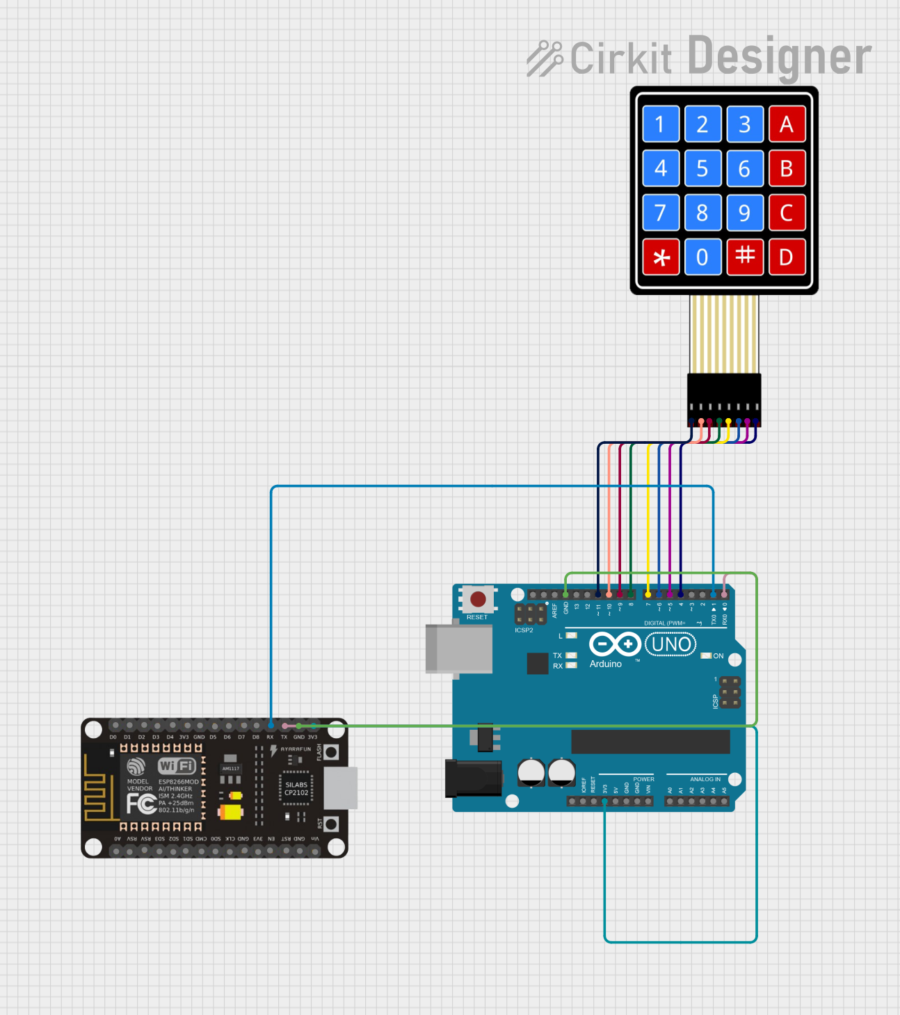
Below is an example code snippet for interfacing the Teensy ELS Keypad with an Arduino UNO. This code assumes a simple 4x4 matrix keypad connected to digital pins 2 through 9.

#include <Keypad.h>

const byte ROWS = 4; // Four rows
const byte COLS = 4; // Four columns

// Define the keymap
char keys[ROWS][COLS] = {
  {'1','2','3','A'},
  {'4','5','6','B'},
  {'7','8','9','C'},
  {'*','0','#','D'}
};

// Connect keypad ROW0, ROW1, ROW2, and ROW3 to these Arduino pins.
byte rowPins[ROWS] = {2, 3, 4, 5};

// Connect keypad COL0, COL1, COL2, and COL3 to these Arduino pins.
byte colPins[COLS] = {6, 7, 8, 9};

// Create the keypad
Keypad keypad = Keypad(makeKeymap(keys), rowPins, colPins, ROWS, COLS);

void setup() {
  Serial.begin(9600);
}

void loop() {
  char key = keypad.getKey();
  
  if (key) {
    Serial.println(key);
  }
}

Remember to adjust the pin numbers and the keymap to match your specific keypad layout and Teensy model.