How to Use 8 Pin Connector: Examples, Pinouts, and Specs

 Design with 8 Pin Connector in Cirkit Designer
Introduction
The 8 Pin Connector by De (Manufacturer Part ID: connection part) is a versatile component designed to establish reliable electrical connections between circuit elements. With its eight pins, this connector is commonly used for both data and power transmission in a wide range of electronic devices. Its robust design ensures durability and consistent performance, making it a popular choice in applications such as communication systems, power distribution, and embedded systems.
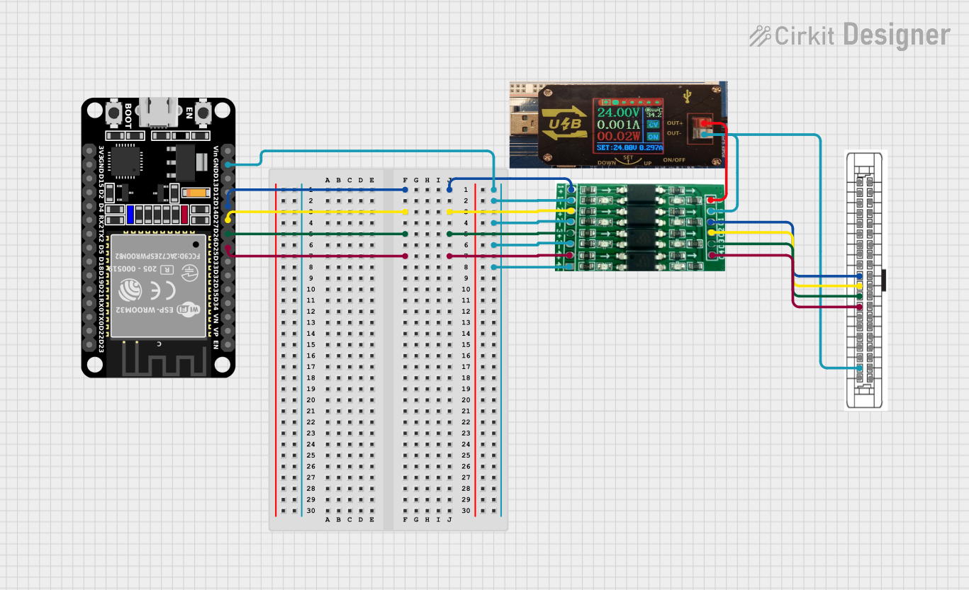
Explore Projects Built with 8 Pin Connector

 Open Project in Cirkit Designer
 Open Project in Cirkit Designer
 Open Project in Cirkit Designer
 Open Project in Cirkit Designer
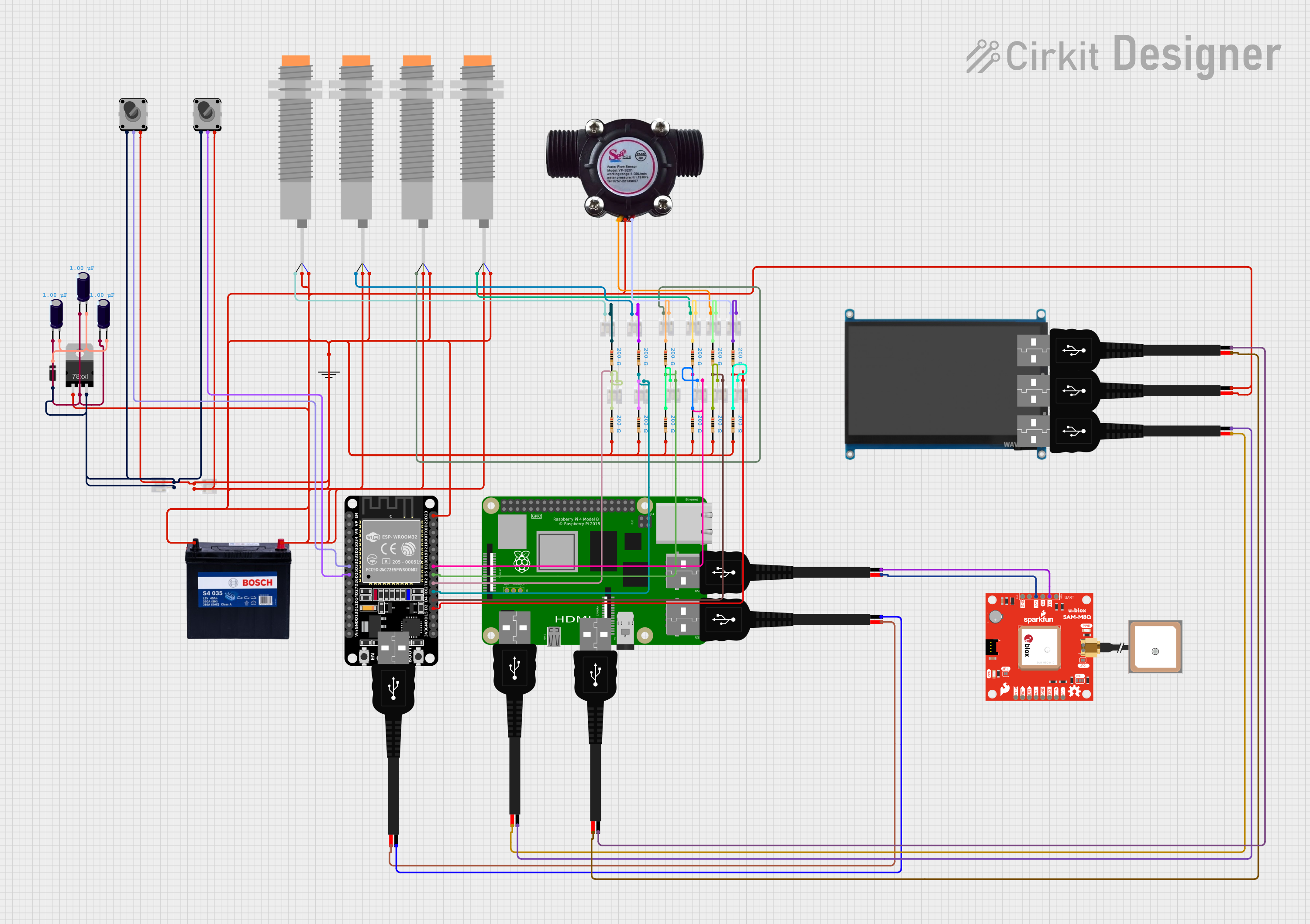
Explore Projects Built with 8 Pin Connector

 Open Project in Cirkit Designer
 Open Project in Cirkit Designer
 Open Project in Cirkit Designer
 Open Project in Cirkit Designer
Common Applications and Use Cases
- Data Transmission: Used in communication devices to transfer signals between components.
- Power Distribution: Facilitates the delivery of power to multiple circuit elements.
- Embedded Systems: Connects microcontrollers, sensors, and actuators in compact designs.
- Consumer Electronics: Found in devices like gaming consoles, audio systems, and home automation products.
Technical Specifications
Key Technical Details
- Number of Pins: 8
- Rated Voltage: 250V AC/DC
- Rated Current: 3A per pin
- Contact Resistance: ≤ 20 mΩ
- Insulation Resistance: ≥ 1000 MΩ at 500V DC
- Operating Temperature Range: -40°C to +85°C
- Material: High-quality thermoplastic housing with gold-plated copper alloy contacts
- Mounting Type: Through-hole or surface-mount, depending on the variant
Pin Configuration and Descriptions
The 8 Pin Connector features the following pin layout and descriptions:
| Pin Number | Description | Typical Use |
|---|---|---|
| 1 | Power Supply (+V) | Positive voltage input |
| 2 | Ground (GND) | Common ground connection |
| 3 | Data Line 1 (D1) | Signal transmission line 1 |
| 4 | Data Line 2 (D2) | Signal transmission line 2 |
| 5 | Data Line 3 (D3) | Signal transmission line 3 |
| 6 | Data Line 4 (D4) | Signal transmission line 4 |
| 7 | Reserved/Custom Use | User-defined functionality |
| 8 | Reserved/Custom Use | User-defined functionality |
Note: Pins 7 and 8 are often reserved for custom applications, such as additional data lines or auxiliary power.
Usage Instructions
How to Use the Component in a Circuit
- Identify Pin Functions: Refer to the pin configuration table above to understand the purpose of each pin.
- Soldering: If using a through-hole variant, insert the connector into the PCB and solder the pins securely. For surface-mount variants, use a reflow soldering process.
- Wiring: Connect the corresponding wires or PCB traces to the appropriate pins based on your circuit design.
- Testing: Verify the connections using a multimeter to ensure proper continuity and insulation.
Important Considerations and Best Practices
- Avoid Overloading: Do not exceed the rated voltage (250V) or current (3A per pin) to prevent damage.
- Proper Alignment: Ensure the connector is properly aligned with its counterpart to avoid bent pins or poor connections.
- Environmental Conditions: Use the connector within the specified operating temperature range (-40°C to +85°C) to maintain performance.
- Secure Mounting: Use screws or clips (if applicable) to secure the connector in place and prevent accidental disconnection.
Example: Connecting to an Arduino UNO
The 8 Pin Connector can be used to interface an Arduino UNO with external components. Below is an example of connecting four data lines and power:
Circuit Diagram
- Pin 1: Connect to Arduino 5V pin
- Pin 2: Connect to Arduino GND pin
- Pins 3-6: Connect to Arduino digital pins (e.g., D2, D3, D4, D5)
Sample Code
// Example code for using the 8 Pin Connector with an Arduino UNO
// Pins 3-6 of the connector are connected to Arduino digital pins D2-D5

const int dataPins[] = {2, 3, 4, 5}; // Define Arduino pins connected to the connector

void setup() {
  // Initialize the data pins as outputs
  for (int i = 0; i < 4; i++) {
    pinMode(dataPins[i], OUTPUT);
  }
}

void loop() {
  // Example: Toggle all data pins ON and OFF
  for (int i = 0; i < 4; i++) {
    digitalWrite(dataPins[i], HIGH); // Set pin HIGH
    delay(500);                      // Wait for 500ms
    digitalWrite(dataPins[i], LOW);  // Set pin LOW
    delay(500);                      // Wait for 500ms
  }
}
Tip: Use heat shrink tubing or cable ties to organize wires connected to the 8 Pin Connector for a cleaner setup.
Troubleshooting and FAQs
Common Issues and Solutions
Loose Connections:
- Issue: Pins are not making proper contact.
- Solution: Ensure the connector is fully seated and aligned. Check for bent or damaged pins.
Signal Interference:
- Issue: Data lines experience noise or signal degradation.
- Solution: Use shielded cables and keep data lines away from high-power lines.
Overheating:
- Issue: Connector becomes hot during operation.
- Solution: Verify that the current does not exceed 3A per pin. Improve ventilation if necessary.
Corrosion or Oxidation:
- Issue: Poor conductivity due to environmental exposure.
- Solution: Use connectors with gold-plated contacts and store them in a dry environment.
FAQs
Q: Can I use this connector for high-speed data transmission?
A: Yes, the 8 Pin Connector supports high-speed data transmission, but ensure proper shielding and grounding to minimize interference.Q: Is this connector compatible with breadboards?
A: Yes, the through-hole variant can be used with breadboards, but you may need to solder header pins for a secure connection.Q: Can I use this connector for AC power applications?
A: Yes, the connector is rated for 250V AC, but ensure proper insulation and safety precautions.Q: How do I clean the connector?
A: Use a soft brush or compressed air to remove dust. For stubborn dirt, use isopropyl alcohol and a lint-free cloth.
By following this documentation, you can effectively integrate the 8 Pin Connector into your projects and ensure reliable performance.