Cirkit Designer Logo
Cirkit Designer
Your all-in-one circuit design IDE
Home / 
Component Documentation

How to Use ESP32-C6 Supermini: Examples, Pinouts, and Specs

Image of ESP32-C6 Supermini
Cirkit Designer LogoDesign with ESP32-C6 Supermini in Cirkit Designer

Introduction

The ESP32-C6 Supermini is a state-of-the-art System on Chip (SoC) that integrates Wi-Fi 6 and Bluetooth 5 (LE) technologies, designed for a wide array of applications such as Internet of Things (IoT), wearable technology, and smart home devices. This component stands out for its low-power consumption, secure wireless connections, and high-performance capabilities, making it an ideal choice for developers looking to build advanced, connected projects.

Explore Projects Built with ESP32-C6 Supermini

Use Cirkit Designer to design, explore, and prototype these projects online. Some projects support real-time simulation. Click "Open Project" to start designing instantly!
ESP32C3 Supermini-Based Smart Environment Monitor and Lighting Control System
Image of Bedside RGB and Lamp: A project utilizing ESP32-C6 Supermini in a practical application
This is a smart control system featuring an ESP32C3 Supermini microcontroller for interfacing with various sensors and actuators. It includes temperature and humidity sensing, RGB LED strip control, user input via a pushbutton and rotary encoder, and AC power control through a two-channel relay. The system is powered by an AC source converted to DC by the HLK-PM12 module.
Cirkit Designer LogoOpen Project in Cirkit Designer
ESP32-C6 and ST7735S Display: Wi-Fi Controlled TFT Display Module
Image of ESP32-C6sm-ST7735: A project utilizing ESP32-C6 Supermini in a practical application
This circuit features an ESP32-C6 microcontroller interfaced with a China ST7735S 160x128 TFT display. The ESP32-C6 controls the display via SPI communication, providing power, ground, and control signals to render graphics and text on the screen.
Cirkit Designer LogoOpen Project in Cirkit Designer
ESP32C3 and LoRa-Enabled Environmental Sensing Node
Image of temperature_KA: A project utilizing ESP32-C6 Supermini in a practical application
This circuit features an ESP32C3 Supermini microcontroller connected to a LORA_RA02 module and a DHT11 temperature and humidity sensor. The ESP32C3 handles communication with the LORA module via SPI (using GPIO05, GPIO06, GPIO10, and GPIO04 for MISO, MOSI, NSS, and SCK respectively) and GPIO01 and GPIO02 for additional control signals. The DHT11 sensor is interfaced through GPIO03 for data reading, and all components share a common power supply through the 3.3V and GND pins.
Cirkit Designer LogoOpen Project in Cirkit Designer
ESP32-C3 and Micro SD Card Module for Data Logging
Image of Esp 32 super mini with MicroSd module: A project utilizing ESP32-C6 Supermini in a practical application
This circuit features an ESP32-C3 microcontroller interfaced with a Micro SD Card Module. The ESP32-C3 handles SPI communication with the SD card for data storage and retrieval, with specific GPIO pins assigned for MOSI, MISO, SCK, and CS signals.
Cirkit Designer LogoOpen Project in Cirkit Designer

Explore Projects Built with ESP32-C6 Supermini

Use Cirkit Designer to design, explore, and prototype these projects online. Some projects support real-time simulation. Click "Open Project" to start designing instantly!
Image of Bedside RGB and Lamp: A project utilizing ESP32-C6 Supermini in a practical application
ESP32C3 Supermini-Based Smart Environment Monitor and Lighting Control System
This is a smart control system featuring an ESP32C3 Supermini microcontroller for interfacing with various sensors and actuators. It includes temperature and humidity sensing, RGB LED strip control, user input via a pushbutton and rotary encoder, and AC power control through a two-channel relay. The system is powered by an AC source converted to DC by the HLK-PM12 module.
Cirkit Designer LogoOpen Project in Cirkit Designer
Image of ESP32-C6sm-ST7735: A project utilizing ESP32-C6 Supermini in a practical application
ESP32-C6 and ST7735S Display: Wi-Fi Controlled TFT Display Module
This circuit features an ESP32-C6 microcontroller interfaced with a China ST7735S 160x128 TFT display. The ESP32-C6 controls the display via SPI communication, providing power, ground, and control signals to render graphics and text on the screen.
Cirkit Designer LogoOpen Project in Cirkit Designer
Image of temperature_KA: A project utilizing ESP32-C6 Supermini in a practical application
ESP32C3 and LoRa-Enabled Environmental Sensing Node
This circuit features an ESP32C3 Supermini microcontroller connected to a LORA_RA02 module and a DHT11 temperature and humidity sensor. The ESP32C3 handles communication with the LORA module via SPI (using GPIO05, GPIO06, GPIO10, and GPIO04 for MISO, MOSI, NSS, and SCK respectively) and GPIO01 and GPIO02 for additional control signals. The DHT11 sensor is interfaced through GPIO03 for data reading, and all components share a common power supply through the 3.3V and GND pins.
Cirkit Designer LogoOpen Project in Cirkit Designer
Image of Esp 32 super mini with MicroSd module: A project utilizing ESP32-C6 Supermini in a practical application
ESP32-C3 and Micro SD Card Module for Data Logging
This circuit features an ESP32-C3 microcontroller interfaced with a Micro SD Card Module. The ESP32-C3 handles SPI communication with the SD card for data storage and retrieval, with specific GPIO pins assigned for MOSI, MISO, SCK, and CS signals.
Cirkit Designer LogoOpen Project in Cirkit Designer

Common Applications and Use Cases

  • Smart home devices (e.g., smart plugs, lighting systems)
  • Wearable technology (e.g., fitness trackers, smartwatches)
  • IoT sensors and actuators
  • Wireless communication hubs
  • Remote monitoring and control systems

Technical Specifications

Key Technical Details

  • CPU: 32-bit RISC-V single-core processor
  • Wi-Fi: IEEE 802.11ax (Wi-Fi 6)
  • Bluetooth: Bluetooth 5 (LE)
  • RAM: Integrated SRAM
  • Flash Memory: Support for external QSPI flash
  • GPIO: Multiple GPIO pins with various functions
  • Voltage: 3.0V to 3.6V
  • Current: Varies with operating modes
  • Power Ratings: Low-power modes available for battery-powered applications

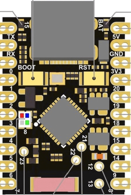
Pin Configuration and Descriptions

Pin Number Name Type Description
1 GND P Ground connection
2 3V3 P 3.3V power supply input
3 EN I Chip enable (active high)
... ... ... ...
n IOx I/O General-purpose input/output pin x
  • P: Power
  • I: Input
  • O: Output
  • I/O: Input/Output

(Note: The above table is a simplified representation. The actual ESP32-C6 Supermini has a more complex pinout that should be referred to in the datasheet for complete details.)

Usage Instructions

How to Use the Component in a Circuit

  1. Power Supply: Connect a stable 3.3V power source to the 3V3 pin and ground to the GND pin.
  2. Boot Mode Selection: Ensure that the IO0 pin is pulled high during normal operation and low to enter bootloader mode.
  3. Antenna Connection: Connect an appropriate antenna to the Wi-Fi/Bluetooth antenna pin for wireless communication.
  4. Peripheral Connections: Connect sensors, actuators, or other peripherals to the GPIO pins as required for your application.

Important Considerations and Best Practices

  • Use a regulated power supply to prevent damage to the SoC.
  • Implement proper decoupling capacitors close to the power pins to ensure stable operation.
  • Avoid exposing the device to temperatures outside the specified operating range.
  • Ensure that the antenna design and placement follow the guidelines for optimal wireless performance.
  • Follow ESD precautions when handling the ESP32-C6 Supermini to prevent static damage.

Troubleshooting and FAQs

Common Issues

  • Device Not Booting: Check the power supply and boot mode pin configuration.
  • Wi-Fi/Bluetooth Not Functioning: Verify the antenna connections and ensure that the device is not in a shielded enclosure.
  • Unexpected Behavior in Peripherals: Double-check the GPIO configurations and ensure that peripherals are compatible and correctly connected.

Solutions and Tips for Troubleshooting

  • Use a multimeter to verify the power supply voltage and pin states.
  • Consult the ESP32-C6 Supermini datasheet for detailed pin descriptions and functional diagrams.
  • Use serial output to debug and track the boot process and error messages.

FAQs

Q: Can the ESP32-C6 Supermini be used with a battery? A: Yes, the ESP32-C6 Supermini is designed for low-power applications and can be powered by a battery.

Q: Does the ESP32-C6 Supermini support Arduino IDE? A: Support for the Arduino IDE can vary. Check the latest resources provided by Espressif or the community for compatibility and setup instructions.

Q: How can I update the firmware on the ESP32-C6 Supermini? A: Firmware updates can be done via the UART interface using the bootloader mode or over-the-air (OTA) if Wi-Fi is configured.

Q: What is the maximum range of Wi-Fi and Bluetooth on the ESP32-C6 Supermini? A: The range depends on several factors, including antenna design, output power settings, and environmental conditions. Refer to the datasheet for detailed specifications.


For any additional information or support, refer to the manufacturer's official documentation or contact their technical support team.