
Cirkit Designer
Your all-in-one circuit design IDE
Home /
Component Documentation
How to Use relay_5V: Examples, Pinouts, and Specs
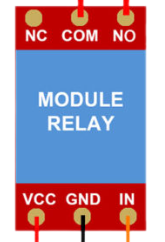
 Design with relay_5V in Cirkit Designer
Introduction
A 5V relay is an electromechanical switch that uses an electromagnetic coil to open or close contacts. It allows a low voltage signal (5V) to control high voltage or high current circuits, making it an essential component in automation, home appliances, and industrial control systems.
Explore Projects Built with relay_5V
Arduino UNO Controlled 5V Relay Switch
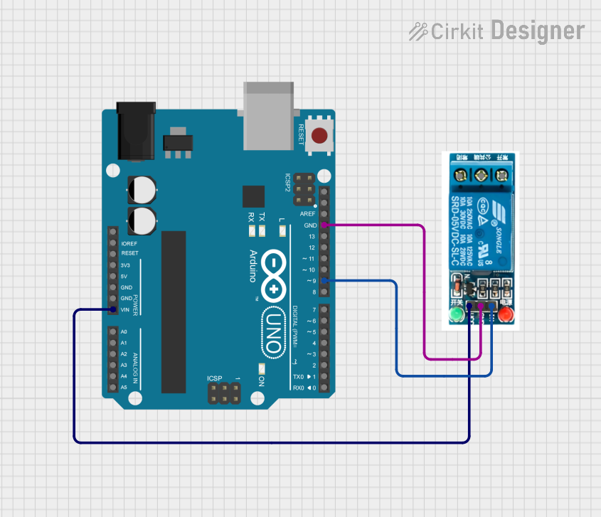
This circuit uses an Arduino UNO to control a 5V relay. The relay is powered by the Arduino's Vin and GND pins, and its control input is connected to digital pin D9 on the Arduino. The provided code is a basic template with no specific functionality implemented.
Open Project in Cirkit DesignerBattery-Powered LED Control with Pushbutton and Relay
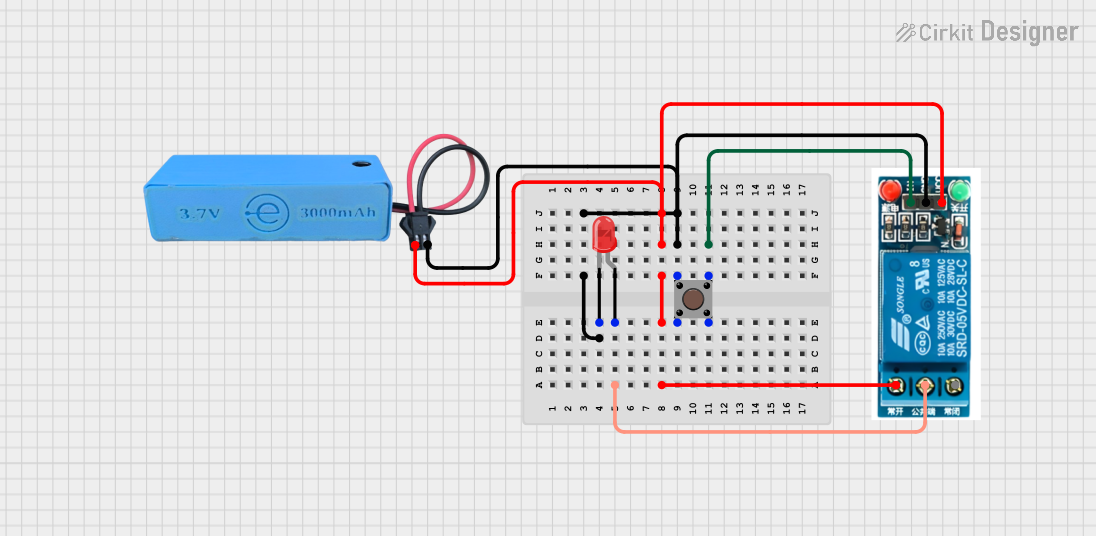
This circuit uses a pushbutton to control a 5V relay, which in turn powers a red LED. The MAHIR 1.mini module provides the necessary 3.7V power supply, and the relay switches the LED on and off based on the pushbutton input.
Open Project in Cirkit DesignerWeMos D1 R2 Controlled Relay Switching Circuit for AC Bulb and USB Charger
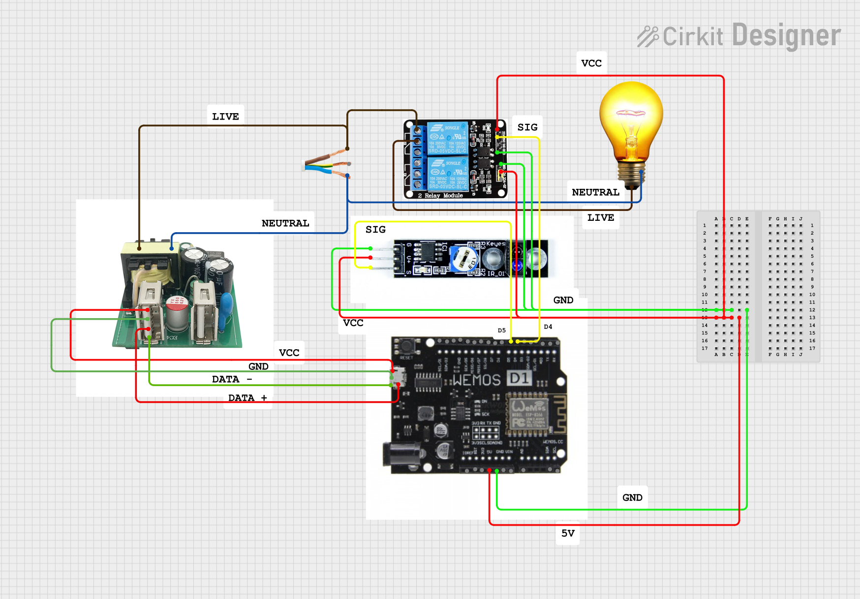
This circuit uses a WeMos D1 R2 microcontroller to control a 5V 2-relay module, which in turn controls the power to an AC bulb and a cellphone charger. The microcontroller also interfaces with a line tracking sensor, which likely provides input to control the relay states. The AC bulb and cellphone charger are powered by an AC wire connection, with the relay acting as a switch for the bulb.
Open Project in Cirkit DesignerBattery-Powered 4-Channel Relay Control with LED Indicators
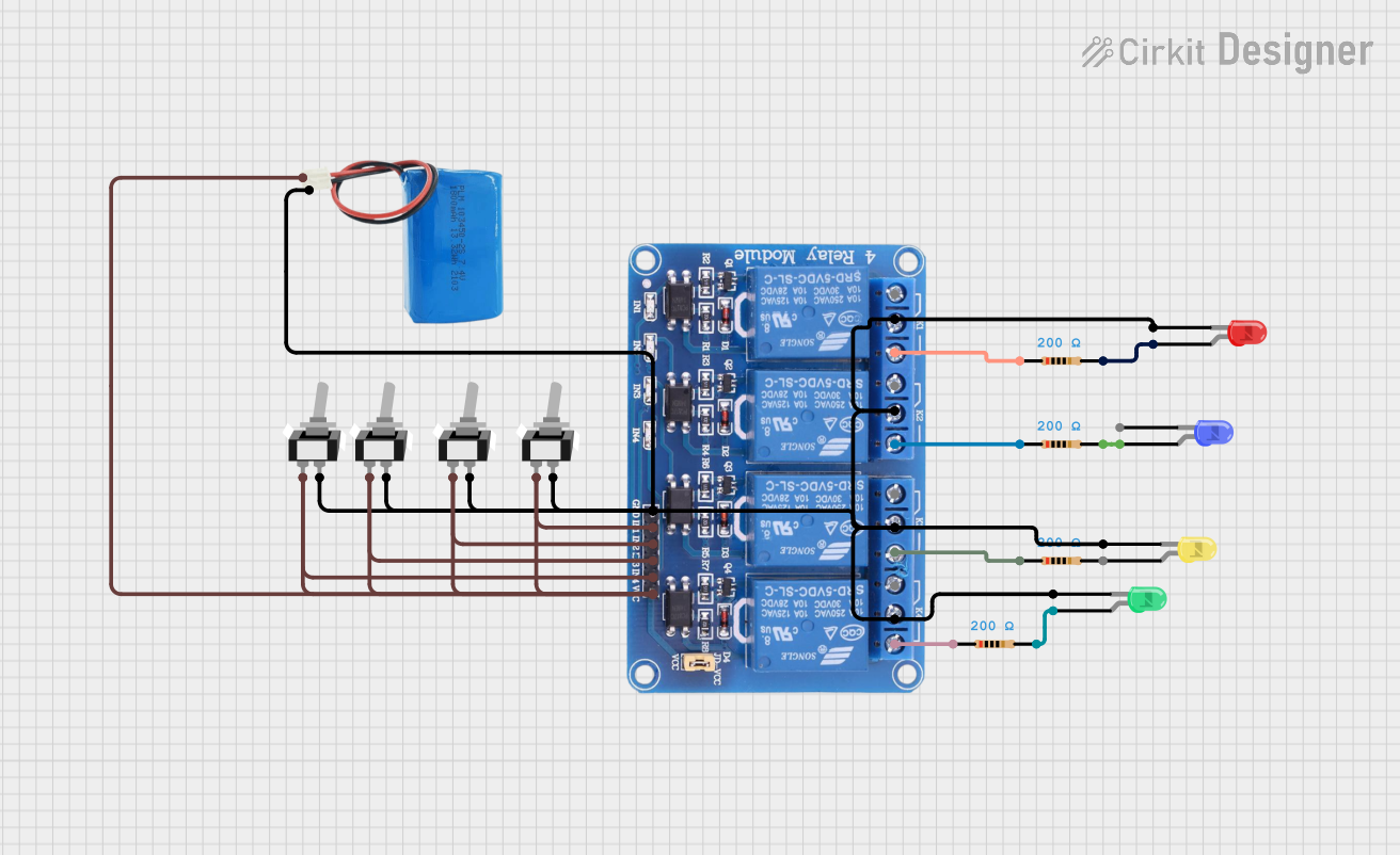
This circuit consists of a 5V battery powering a 4-channel relay module, which controls four LEDs (red, yellow, green, and blue) through individual resistors. Each relay channel is activated by a corresponding SPST toggle switch, allowing manual control of the LEDs.
Open Project in Cirkit DesignerExplore Projects Built with relay_5V
Arduino UNO Controlled 5V Relay Switch
This circuit uses an Arduino UNO to control a 5V relay. The relay is powered by the Arduino's Vin and GND pins, and its control input is connected to digital pin D9 on the Arduino. The provided code is a basic template with no specific functionality implemented.
Open Project in Cirkit DesignerBattery-Powered LED Control with Pushbutton and Relay
This circuit uses a pushbutton to control a 5V relay, which in turn powers a red LED. The MAHIR 1.mini module provides the necessary 3.7V power supply, and the relay switches the LED on and off based on the pushbutton input.
Open Project in Cirkit DesignerWeMos D1 R2 Controlled Relay Switching Circuit for AC Bulb and USB Charger
This circuit uses a WeMos D1 R2 microcontroller to control a 5V 2-relay module, which in turn controls the power to an AC bulb and a cellphone charger. The microcontroller also interfaces with a line tracking sensor, which likely provides input to control the relay states. The AC bulb and cellphone charger are powered by an AC wire connection, with the relay acting as a switch for the bulb.
Open Project in Cirkit DesignerBattery-Powered 4-Channel Relay Control with LED Indicators
This circuit consists of a 5V battery powering a 4-channel relay module, which controls four LEDs (red, yellow, green, and blue) through individual resistors. Each relay channel is activated by a corresponding SPST toggle switch, allowing manual control of the LEDs.
Open Project in Cirkit DesignerCommon Applications and Use Cases
- Home automation (e.g., controlling lights or fans)
- Industrial equipment control
- Motor control circuits
- Microcontroller-based projects (e.g., Arduino, Raspberry Pi)
- Safety systems (e.g., isolating high voltage circuits)
Technical Specifications
Below are the key technical details for a standard 5V relay:
| Parameter | Value |
|---|---|
| Operating Voltage | 5V DC |
| Trigger Voltage | 3.75V to 5V DC |
| Coil Resistance | ~70Ω to 100Ω |
| Switching Voltage (Max) | 250V AC / 30V DC |
| Switching Current (Max) | 10A |
| Contact Type | SPDT (Single Pole Double Throw) |
| Isolation | Electrical isolation between coil and contacts |
| Dimensions | Varies by model (e.g., 28mm x 10mm x 15mm) |
Pin Configuration and Descriptions
The 5V relay typically has 5 pins. Below is the pin configuration:
| Pin Name | Description |
|---|---|
| Coil+ | Positive terminal of the relay coil (connect to 5V DC) |
| Coil- | Negative terminal of the relay coil (connect to ground) |
| Common (COM) | Common terminal for the relay switch |
| Normally Open (NO) | Open circuit when the relay is inactive; closes when the relay is activated |
| Normally Closed (NC) | Closed circuit when the relay is inactive; opens when the relay is activated |
Usage Instructions
How to Use the Component in a Circuit
- Power the Relay Coil: Connect the
Coil+pin to a 5V DC power source and theCoil-pin to ground. This energizes the relay coil. - Control the Relay: Use a microcontroller (e.g., Arduino) or a transistor to control the relay coil. A low voltage signal (5V) can activate the relay.
- Connect the Load:
- Connect the high voltage or high current load to the
COMandNOorNCpins, depending on the desired behavior:- Use
NOif the load should be off by default and turn on when the relay is activated. - Use
NCif the load should be on by default and turn off when the relay is activated.
- Use
- Connect the high voltage or high current load to the
- Add Protection: Place a flyback diode across the relay coil terminals to protect the circuit from voltage spikes when the relay is deactivated.
Important Considerations and Best Practices
- Isolation: Ensure proper electrical isolation between the low voltage control circuit and the high voltage load.
- Flyback Diode: Always use a flyback diode (e.g., 1N4007) across the relay coil to prevent damage to the control circuit.
- Current Ratings: Do not exceed the relay's maximum current and voltage ratings.
- Heat Dissipation: If switching high currents, ensure adequate ventilation or heat dissipation to prevent overheating.
- Debouncing: Use software or hardware debouncing to avoid relay chatter caused by noise or unstable signals.
Example: Connecting a 5V Relay to an Arduino UNO
Below is an example of how to control a 5V relay using an Arduino UNO:
// Define the relay control pin
const int relayPin = 7; // Connect this pin to the relay's Coil+ via a transistor

void setup() {
  pinMode(relayPin, OUTPUT); // Set the relay pin as an output
  digitalWrite(relayPin, LOW); // Ensure the relay is off initially
}

void loop() {
  digitalWrite(relayPin, HIGH); // Activate the relay
  delay(1000); // Keep the relay on for 1 second
  digitalWrite(relayPin, LOW); // Deactivate the relay
  delay(1000); // Keep the relay off for 1 second
}
Circuit Notes:
- Use a transistor (e.g., 2N2222) to drive the relay, as the Arduino pin cannot supply enough current directly.
- Connect a flyback diode (e.g., 1N4007) across the relay coil terminals to protect the transistor and Arduino from voltage spikes.
Troubleshooting and FAQs
Common Issues Users Might Face
Relay Not Activating:
- Cause: Insufficient voltage or current to the relay coil.
- Solution: Verify that the control signal is 5V and the power supply can provide enough current.
Relay Chattering or Flickering:
- Cause: Unstable control signal or insufficient power supply.
- Solution: Use a capacitor to stabilize the power supply and implement software/hardware debouncing.
Load Not Switching:
- Cause: Incorrect wiring of the load to the
COM,NO, orNCpins. - Solution: Double-check the wiring and ensure the load is connected to the correct pins.
- Cause: Incorrect wiring of the load to the
Burnt Relay or Circuit Damage:
- Cause: Exceeding the relay's voltage or current ratings.
- Solution: Ensure the load does not exceed the relay's maximum ratings.
Solutions and Tips for Troubleshooting
- Use a multimeter to check the continuity of the relay contacts (
COM,NO,NC) when the relay is activated or deactivated. - Test the relay coil by directly applying 5V to the
Coil+andCoil-pins to ensure it is functional. - If using a microcontroller, verify the control signal with an oscilloscope or logic analyzer to ensure it is stable and within the required voltage range.
By following this documentation, you can effectively integrate and troubleshoot a 5V relay in your electronic projects.