
How to Use RS Pro 1-row ab male 32 pins: Examples, Pinouts, and Specs

 Design with RS Pro 1-row ab male 32 pins in Cirkit Designer
Introduction
The RS Pro 1-row AB Male 32 Pins connector is a versatile and reliable electronic component designed for connecting various electronic devices and circuits. With its single-row, 32-pin configuration, it is ideal for applications requiring compact and efficient connections. The standard pin spacing ensures compatibility with most printed circuit boards (PCBs) and breadboards, making it a popular choice for prototyping and production environments.
Explore Projects Built with RS Pro 1-row ab male 32 pins
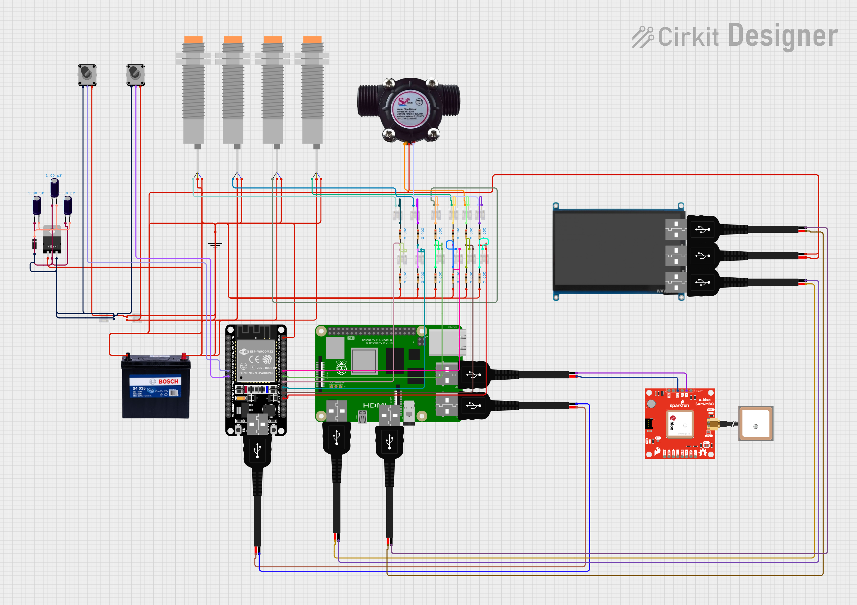 Open Project in Cirkit Designer
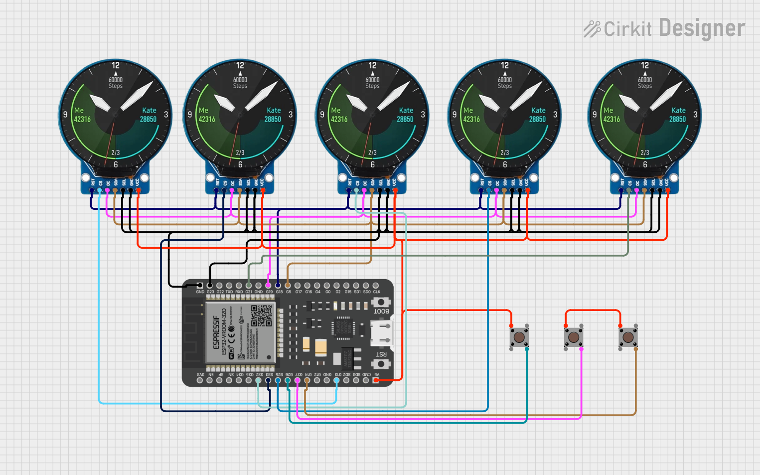 Open Project in Cirkit Designer
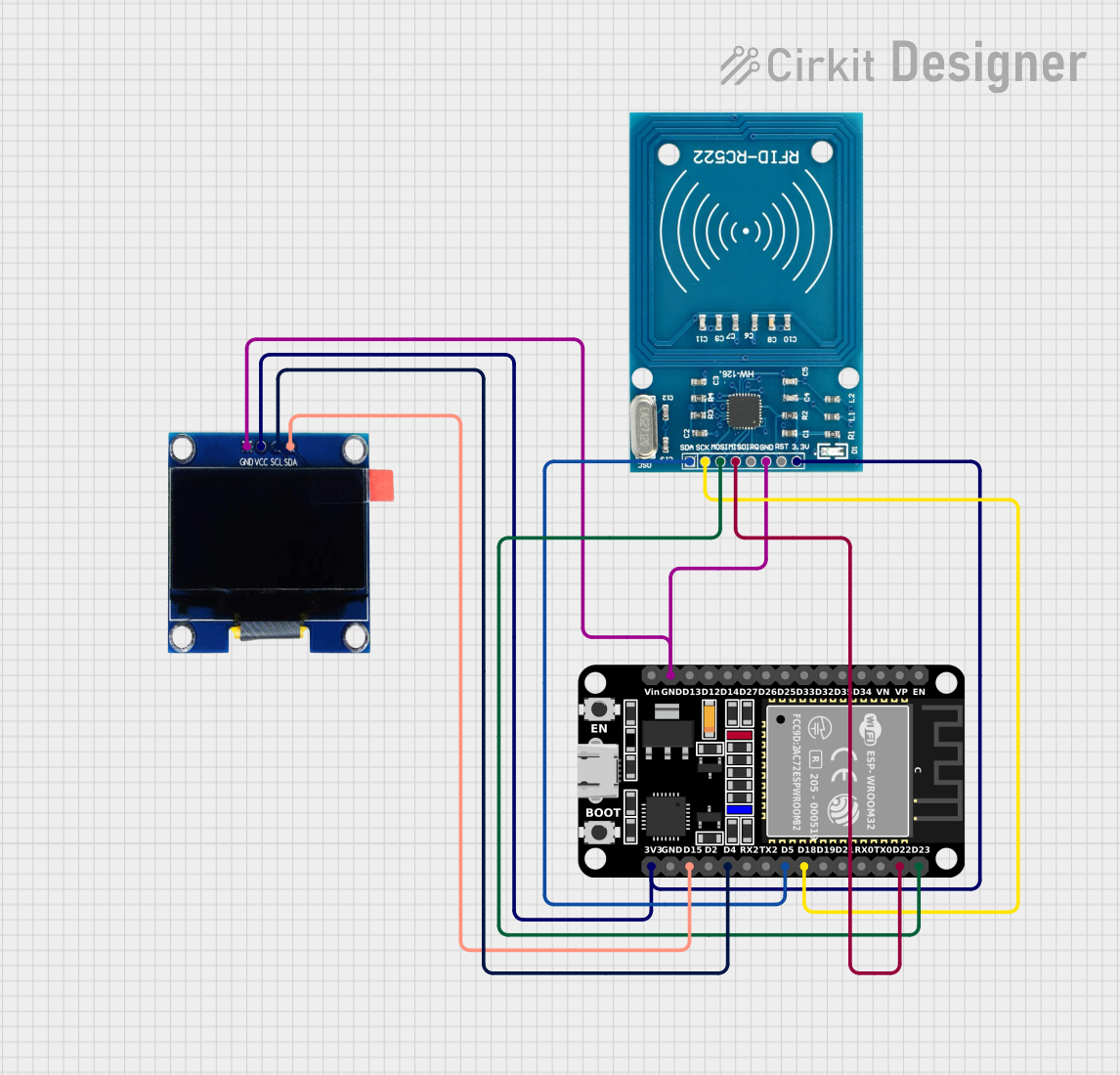 Open Project in Cirkit Designer
 Open Project in Cirkit Designer
Explore Projects Built with RS Pro 1-row ab male 32 pins
Open Project in Cirkit DesignerOpen Project in Cirkit DesignerOpen Project in Cirkit DesignerOpen Project in Cirkit DesignerCommon Applications and Use Cases
- Prototyping and Development: Used in breadboards and PCBs for testing and development.
- Embedded Systems: Connects microcontrollers, sensors, and other peripherals.
- Industrial Electronics: Facilitates connections in control systems and automation equipment.
- Consumer Electronics: Used in devices requiring compact and reliable pin connections.
Technical Specifications
Below are the key technical details of the RS Pro 1-row AB Male 32 Pins connector:
| Parameter | Specification |
|---|---|
| Manufacturer | RS PRO |
| Number of Pins | 32 |
| Pin Configuration | Single row |
| Pin Spacing | 2.54 mm (0.1 inch) |
| Pin Type | Male |
| Material | Gold-plated brass (pins), plastic housing |
| Current Rating | 3 A per pin |
| Voltage Rating | 250 V AC/DC |
| Operating Temperature | -40°C to +105°C |
| Mounting Type | Through-hole or solderable |
Pin Configuration and Descriptions
The RS Pro 1-row AB Male 32 Pins connector features a straightforward pin layout. Each pin is identical and can be used for signal, power, or ground connections as required by the circuit design.
| Pin Number | Description |
|---|---|
| 1–32 | General-purpose pins for signal, power, or ground connections |
Usage Instructions
How to Use the Component in a Circuit
Mounting the Connector:
- Align the connector with the PCB or breadboard, ensuring the pins match the desired layout.
- For PCBs, insert the pins into the through-holes and solder them securely.
- For breadboards, simply press the pins into the breadboard holes.
Connecting Components:
- Use jumper wires or compatible female connectors to link the pins to other components.
- Ensure proper alignment to avoid short circuits or incorrect connections.
Power and Signal Handling:
- Verify the current and voltage ratings of the connector to ensure safe operation.
- Assign specific pins for power, ground, and signal lines to maintain clarity in the circuit.
Important Considerations and Best Practices
- Avoid Overloading: Do not exceed the 3 A current rating or 250 V voltage rating per pin.
- Soldering Tips: Use a soldering iron with a temperature range of 300–350°C for optimal soldering results.
- Pin Protection: Handle the connector carefully to avoid bending or damaging the pins.
- Compatibility Check: Ensure the pin spacing (2.54 mm) matches the PCB or breadboard layout.
Example: Using with an Arduino UNO
The RS Pro 1-row AB Male 32 Pins connector can be used to interface an Arduino UNO with external components. Below is an example of connecting an LED to an Arduino UNO using this connector:
// Example: Blinking an LED using Arduino UNO and RS Pro 1-row AB Male 32 Pins

// Define the pin connected to the LED
const int ledPin = 13; // Pin 13 on Arduino UNO

void setup() {
  pinMode(ledPin, OUTPUT); // Set the LED pin as an output
}

void loop() {
  digitalWrite(ledPin, HIGH); // Turn the LED on
  delay(1000);                // Wait for 1 second
  digitalWrite(ledPin, LOW);  // Turn the LED off
  delay(1000);                // Wait for 1 second
}
Note: Ensure the LED is connected to the appropriate pin on the RS Pro connector, and use a current-limiting resistor (e.g., 220 Ω) to protect the LED.
Troubleshooting and FAQs
Common Issues Users Might Face
Loose Connections:
- Cause: Improper insertion into the breadboard or PCB.
- Solution: Ensure the pins are fully inserted and soldered securely.
Bent or Damaged Pins:
- Cause: Mishandling or excessive force during installation.
- Solution: Straighten bent pins carefully with pliers or replace the connector if necessary.
Short Circuits:
- Cause: Adjacent pins accidentally connected by solder or wires.
- Solution: Inspect the solder joints and remove any excess solder or debris.
Overheating During Soldering:
- Cause: Prolonged exposure to high temperatures.
- Solution: Limit soldering time to 2–3 seconds per pin and use a temperature-controlled soldering iron.
FAQs
Q1: Can this connector be used for high-frequency signals?
A1: Yes, the RS Pro 1-row AB Male 32 Pins connector can handle high-frequency signals, but ensure proper grounding and shielding in your circuit design to minimize interference.
Q2: Is this connector compatible with all breadboards?
A2: The connector is compatible with standard breadboards that have a 2.54 mm pin spacing.
Q3: Can I use this connector for power distribution?
A3: Yes, but ensure the current does not exceed 3 A per pin and distribute the load across multiple pins if necessary.
Q4: How do I clean the connector?
A4: Use a soft brush or compressed air to remove dust. Avoid using liquids that may damage the plastic housing or gold plating.
By following this documentation, users can effectively integrate the RS Pro 1-row AB Male 32 Pins connector into their projects and troubleshoot common issues with ease.