
How to Use SSR: Examples, Pinouts, and Specs
 Design with SSR in Cirkit Designer
Introduction
A Solid State Relay (SSR) is an electronic switching device that uses semiconductor components, such as thyristors, triacs, or transistors, to perform switching operations. Unlike traditional electromechanical relays, SSRs have no moving parts, which allows for faster switching speeds, silent operation, and a significantly longer lifespan. SSRs are widely used in applications where high reliability, noise-free operation, and fast switching are critical.
Explore Projects Built with SSR
 Open Project in Cirkit Designer
 Open Project in Cirkit Designer
 Open Project in Cirkit Designer
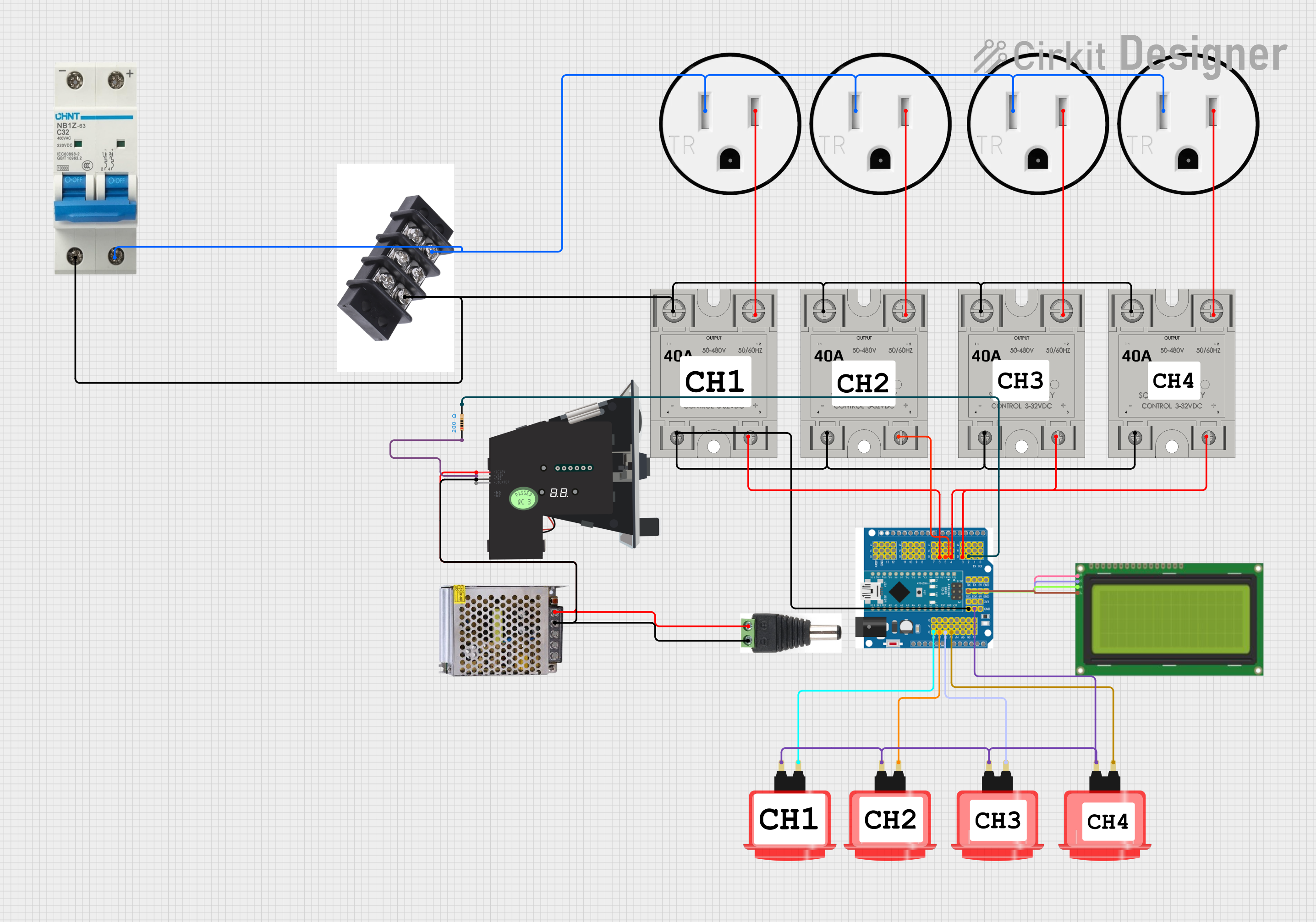 Open Project in Cirkit Designer
Explore Projects Built with SSR
Open Project in Cirkit DesignerOpen Project in Cirkit DesignerOpen Project in Cirkit DesignerOpen Project in Cirkit DesignerCommon Applications and Use Cases
- Industrial automation and control systems
- Heating, ventilation, and air conditioning (HVAC) systems
- Motor control and protection
- Lighting control systems
- Temperature control in ovens and furnaces
- Home appliances and smart home systems
Technical Specifications
Below are the general technical specifications for a typical SSR. Always refer to the datasheet of the specific model for exact details.
Key Technical Details
- Input Voltage (Control Signal): 3–32 VDC (typical range)
- Output Voltage (Load): 24–480 VAC (depending on the model)
- Load Current Rating: 2 A to 100 A (varies by model)
- Switching Type: Zero-crossing or random turn-on
- Isolation Voltage: 2500–4000 V (input to output)
- Switching Speed: Typically <10 ms
- Operating Temperature Range: -30°C to +80°C
Pin Configuration and Descriptions
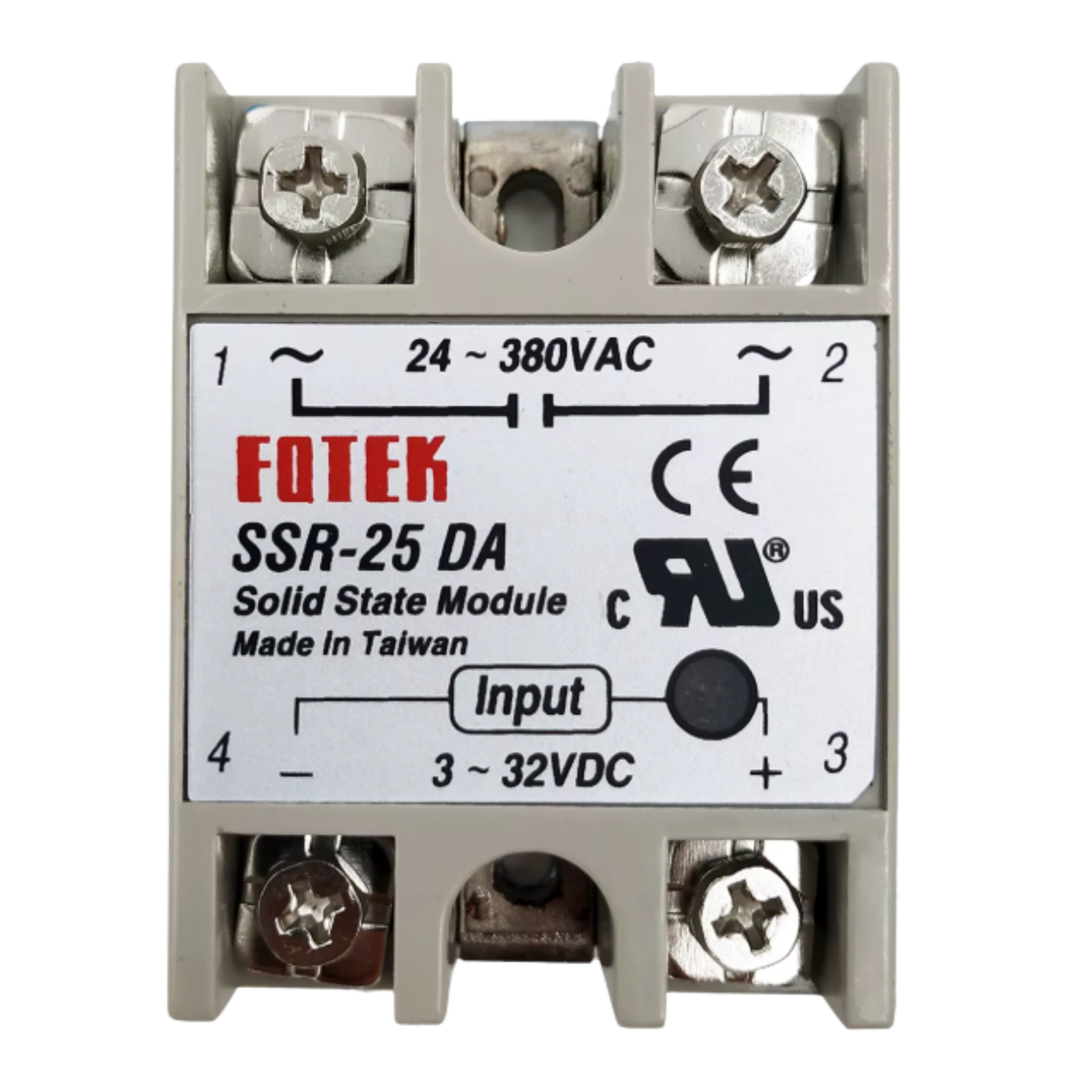
The SSR typically has four terminals: two for the input (control side) and two for the output (load side). Below is a table describing the pin configuration:
| Pin Number | Name | Description |
|---|---|---|
| 1 | Input (+) | Positive terminal for the control signal (DC voltage input). |
| 2 | Input (-) | Negative terminal for the control signal (DC ground). |
| 3 | Output (Load +) | Positive terminal for the AC load connection. |
| 4 | Output (Load -) | Negative terminal for the AC load connection. |
Usage Instructions
How to Use the Component in a Circuit
Connect the Control Signal:
- Apply a DC voltage (within the specified range, e.g., 3–32 VDC) to the input terminals (Pin 1 and Pin 2). This voltage activates the SSR and allows current to flow through the load side.
Connect the Load:
- Connect the AC load (e.g., a motor, light, or heater) to the output terminals (Pin 3 and Pin 4). Ensure the load voltage and current are within the SSR's rated specifications.
Power the Circuit:
- Ensure the control signal is applied only when the load is properly connected. The SSR will switch the load on or off based on the presence or absence of the control signal.
Important Considerations and Best Practices
- Heat Dissipation: SSRs generate heat during operation. Use a heatsink or proper ventilation to prevent overheating, especially for high-current loads.
- Snubber Circuit: For inductive loads (e.g., motors), use a snubber circuit to suppress voltage spikes and protect the SSR.
- Zero-Crossing vs. Random Turn-On: Choose a zero-crossing SSR for resistive loads (e.g., heaters) to reduce electrical noise. Use a random turn-on SSR for inductive loads requiring precise timing.
- Isolation: Ensure proper electrical isolation between the control and load sides to prevent damage to sensitive control circuits.
Example: Connecting an SSR to an Arduino UNO
Below is an example of how to control an SSR using an Arduino UNO to switch an AC load.
Circuit Diagram
- Connect the SSR's input terminals to the Arduino:
- Pin 1 (Input +) to Arduino digital pin (e.g., D9).
- Pin 2 (Input -) to Arduino GND.
- Connect the AC load to the SSR's output terminals:
- Pin 3 (Load +) to the live wire of the AC load.
- Pin 4 (Load -) to the neutral wire of the AC load.
Arduino Code
// Define the SSR control pin
const int ssrPin = 9;

void setup() {
  pinMode(ssrPin, OUTPUT); // Set the SSR pin as an output
}

void loop() {
  digitalWrite(ssrPin, HIGH); // Turn the SSR (and load) ON
  delay(5000);               // Keep the load ON for 5 seconds
  digitalWrite(ssrPin, LOW);  // Turn the SSR (and load) OFF
  delay(5000);               // Keep the load OFF for 5 seconds
}
Troubleshooting and FAQs
Common Issues and Solutions
SSR Not Switching the Load:
- Cause: Insufficient control voltage or current.
- Solution: Verify that the control signal voltage is within the SSR's input range (e.g., 3–32 VDC). Ensure the control circuit can supply enough current to activate the SSR.
Overheating of the SSR:
- Cause: Excessive load current or inadequate heat dissipation.
- Solution: Check that the load current does not exceed the SSR's rated capacity. Use a heatsink or cooling fan if necessary.
Load Flickering or Unstable Operation:
- Cause: Noise or interference in the control signal.
- Solution: Use a decoupling capacitor across the input terminals to filter noise. Ensure the control signal is stable.
SSR Fails to Turn Off:
- Cause: Leakage current in the SSR.
- Solution: Verify the load's minimum operating current. If the load is too small, add a dummy load (e.g., a resistor) in parallel to ensure proper operation.
FAQs
Q: Can an SSR be used with DC loads?
A: Most SSRs are designed for AC loads. For DC loads, use a DC-specific SSR.
Q: What is the difference between zero-crossing and random turn-on SSRs?
A: Zero-crossing SSRs switch the load on when the AC voltage crosses zero, reducing electrical noise. Random turn-on SSRs switch the load on immediately when the control signal is applied, suitable for applications requiring precise timing.
Q: How do I protect the SSR from voltage spikes?
A: Use a snubber circuit or a varistor across the output terminals to suppress voltage spikes, especially for inductive loads.
Q: Can I use an SSR to control high-power devices?
A: Yes, but ensure the SSR's voltage and current ratings match or exceed the requirements of the high-power device. Use proper heat dissipation methods for high-current applications.