How to Use Adafruit Ultimate GPS HAT: Examples, Pinouts, and Specs
Introduction
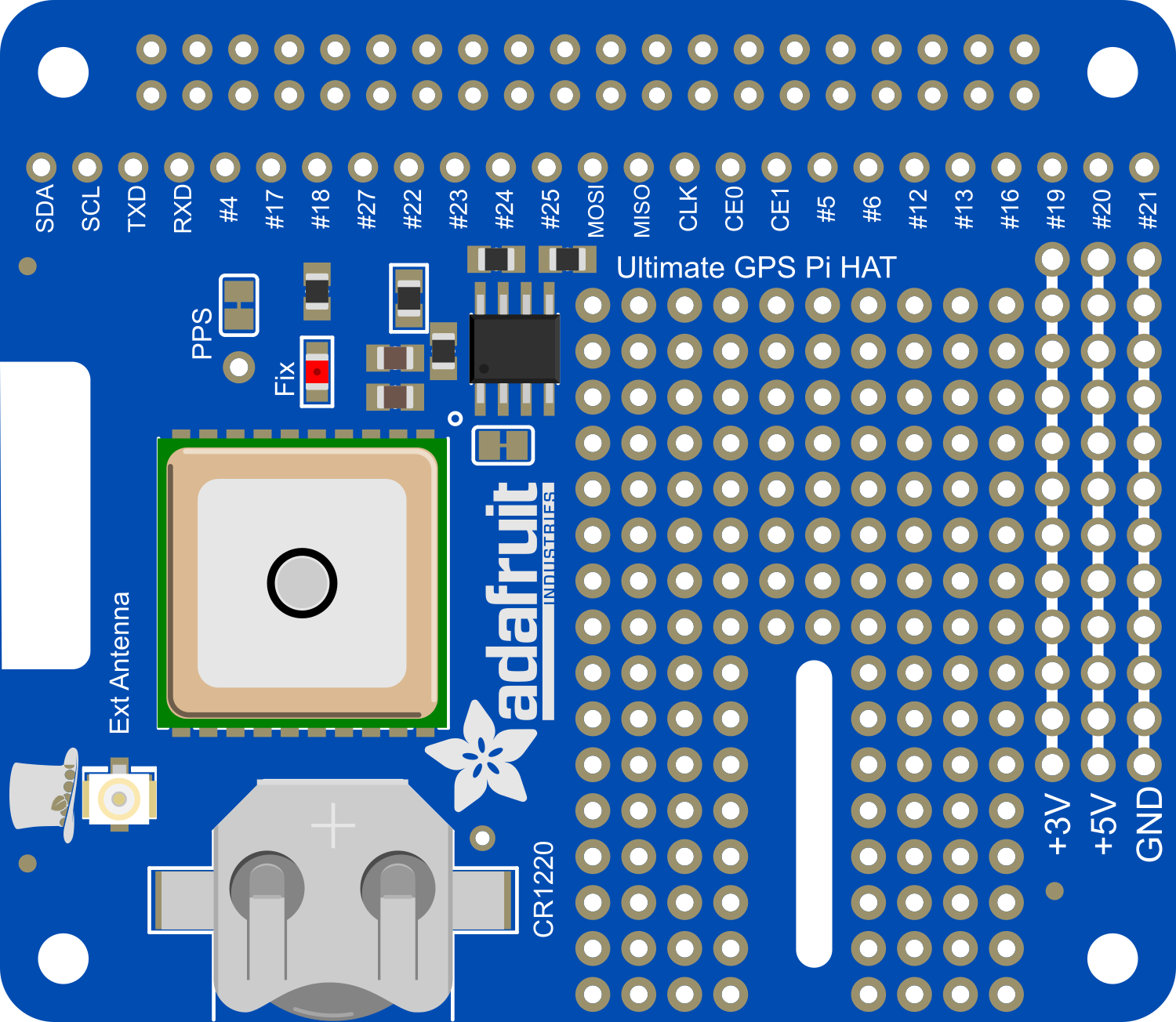
The Adafruit Ultimate GPS HAT is an add-on for the Raspberry Pi that provides high-quality GPS functionality. It is designed to make GPS projects with the Raspberry Pi easy and straightforward. With its high-sensitivity receiver and built-in antenna, it is capable of providing precise positioning, speed, and time data. This GPS module is ideal for a wide range of applications, including but not limited to, geocaching, vehicle tracking, and time synchronization.
Explore Projects Built with Adafruit Ultimate GPS HAT
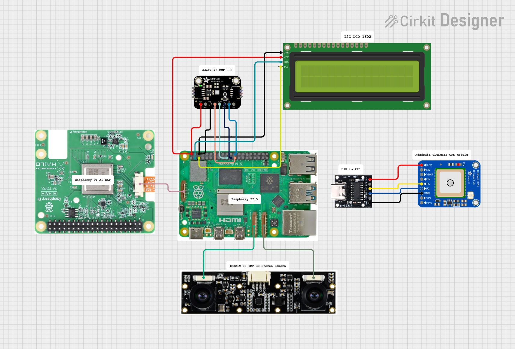
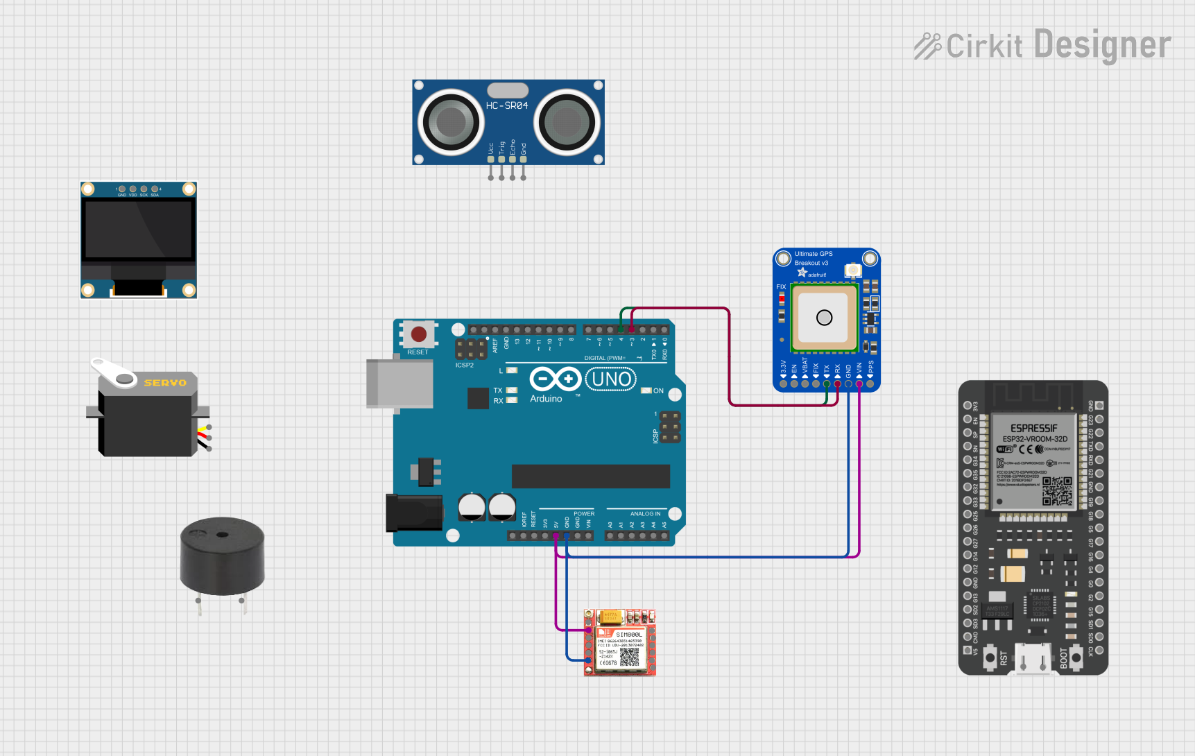


Explore Projects Built with Adafruit Ultimate GPS HAT
Technical Specifications
Key Technical Details
- Satellite Tracking: Tracks up to 22 satellites on 66 channels
- Update Rate: Up to 10 Hz
- Sensitivity: -165 dBm
- Operating Voltage: 3.3V
- Antenna: Built-in patch; u.FL connector for external active antenna
- Protocol: NMEA 0183 and proprietary binary
- Battery: Rechargeable 3.7V lithium battery for memory backup
- Interface: UART at 9600 bps default (adjustable)
Pin Configuration and Descriptions
| Pin Number | Name | Description |
|---|---|---|
| 1 | VCC | Power supply (3.3V input) |
| 2 | RX | UART Receive pin |
| 3 | TX | UART Transmit pin |
| 4 | GND | Ground connection |
| 5 | PPS | Pulse Per Second output |
| 6 | EN | Enable pin for GPS module |
Usage Instructions
Integration with Raspberry Pi
- Mounting the HAT: Attach the Adafruit Ultimate GPS HAT to the GPIO header of the Raspberry Pi.
- Power Supply: Ensure that the Raspberry Pi is powered with a stable 5V supply.
- Software Setup: Install the necessary libraries and software to communicate with the GPS module.
- Serial Communication: The GPS HAT communicates over UART. Make sure to configure the Raspberry Pi's UART settings appropriately.
Important Considerations and Best Practices
- Antenna Placement: For best performance, ensure that the GPS HAT has a clear view of the sky.
- External Antenna: If using an external antenna, connect it to the u.FL connector.
- Power Management: Be mindful of power consumption, especially when running on battery.
- Data Parsing: Familiarize yourself with the NMEA protocol to parse the GPS data effectively.
Troubleshooting and FAQs
Common Issues
- No GPS Fix: Ensure clear sky visibility and check antenna connections.
- Inaccurate Data: Verify that the GPS HAT has been given sufficient time to acquire a fix.
- Serial Communication Errors: Check the UART configuration and baud rate settings.
Solutions and Tips
- Wait for a Fix: It may take several minutes for the GPS to get a fix when first powered on.
- Check Connections: Ensure that the HAT is properly seated on the Raspberry Pi GPIO pins.
- Update Software: Keep the GPS module's firmware and the Raspberry Pi's libraries up to date.
FAQs
Q: Can I use the GPS HAT indoors?
- A: GPS signals are weak indoors. Use an external antenna with a clear view of the sky for best results.
Q: What is the battery for?
- A: The battery maintains the time and satellite data to allow for a quicker fix next time the GPS is powered on.
Q: How do I change the baud rate?
- A: The baud rate can be changed through software commands. Refer to the module's datasheet for specific instructions.
Example Code for Raspberry Pi
Below is a simple Python script to read data from the Adafruit Ultimate GPS HAT using the Raspberry Pi. This script assumes that you have already configured the UART on the Raspberry Pi and installed the necessary Python libraries.
import serial
import time
Initialize serial connection to the GPS HAT
ser = serial.Serial('/dev/serial0', 9600, timeout=1)
Function to read and print GPS data
def read_gps_data(): try: while True: data = ser.readline().decode('ascii', errors='replace') if data.startswith('$GPGGA'): # GPGGA sentence contains position data print(data) time.sleep(0.1) except KeyboardInterrupt: ser.close() # Close serial port when done
Run the function
read_gps_data()
Remember to install the `pyserial` library if you haven't already, using the following command:

```shell
pip install pyserial
This script continuously reads data from the GPS module and prints out the GPGGA sentences, which contain the position information. You can parse these sentences to extract the latitude, longitude, and other relevant data for your application.