
How to Use ir sensor: Examples, Pinouts, and Specs
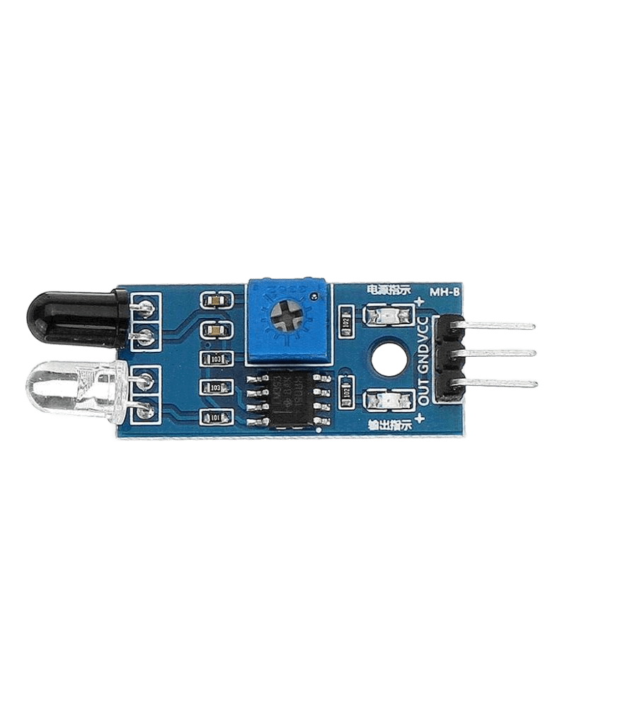
 Design with ir sensor in Cirkit Designer
Introduction
An infrared (IR) sensor detects infrared radiation, which is electromagnetic radiation with wavelengths longer than visible light. IR sensors are widely used in various applications, including proximity sensing, motion detection, and remote control systems. These sensors are versatile, cost-effective, and easy to integrate into electronic circuits, making them a popular choice for hobbyists and professionals alike.
Common applications of IR sensors include:
- Obstacle detection in robotics
- Line-following robots
- Motion detection for security systems
- Remote control signal reception
- Non-contact temperature measurement
Explore Projects Built with ir sensor
 Open Project in Cirkit Designer
 Open Project in Cirkit Designer
 Open Project in Cirkit Designer
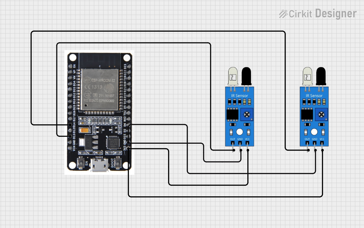 Open Project in Cirkit Designer
Explore Projects Built with ir sensor
Open Project in Cirkit DesignerOpen Project in Cirkit DesignerOpen Project in Cirkit DesignerOpen Project in Cirkit DesignerTechnical Specifications
Below are the general technical specifications for a typical IR sensor module:
| Parameter | Value |
|---|---|
| Operating Voltage | 3.3V to 5V |
| Operating Current | 20mA (typical) |
| Detection Range | 2cm to 30cm (varies by model) |
| Output Type | Digital (High/Low) or Analog |
| Wavelength Sensitivity | ~940nm (infrared spectrum) |
| Response Time | ~10ms |
| Operating Temperature | -25°C to 85°C |
Pin Configuration
The pin configuration for a standard 3-pin IR sensor module is as follows:
| Pin | Name | Description |
|---|---|---|
| 1 | VCC | Power supply pin (3.3V to 5V) |
| 2 | GND | Ground pin |
| 3 | OUT | Output pin (Digital or Analog, depending on the model) |
Usage Instructions
How to Use the IR Sensor in a Circuit
- Power the Sensor: Connect the VCC pin to a 3.3V or 5V power source and the GND pin to the ground of your circuit.
- Connect the Output: Attach the OUT pin to a microcontroller's input pin (e.g., Arduino) or to another circuit component, such as an LED or buzzer.
- Adjust Sensitivity (if applicable): Many IR sensor modules include a potentiometer to adjust the detection range. Turn the potentiometer clockwise or counterclockwise to fine-tune the sensitivity.
- Test the Sensor: Place an object within the detection range of the sensor and observe the output signal. For digital sensors, the output will typically go HIGH (1) when an object is detected and LOW (0) otherwise.
Important Considerations and Best Practices
- Ambient Light Interference: IR sensors can be affected by strong ambient light sources, such as sunlight. Use the sensor in controlled lighting conditions or shield it from direct light.
- Reflective Surfaces: The sensor's performance may vary depending on the reflectivity of the object being detected. Highly reflective surfaces improve detection, while dark or matte surfaces may reduce sensitivity.
- Power Supply Stability: Ensure a stable power supply to avoid erratic behavior.
- Distance Calibration: If the sensor includes a potentiometer, calibrate it for the specific range required by your application.
Example: Connecting an IR Sensor to an Arduino UNO
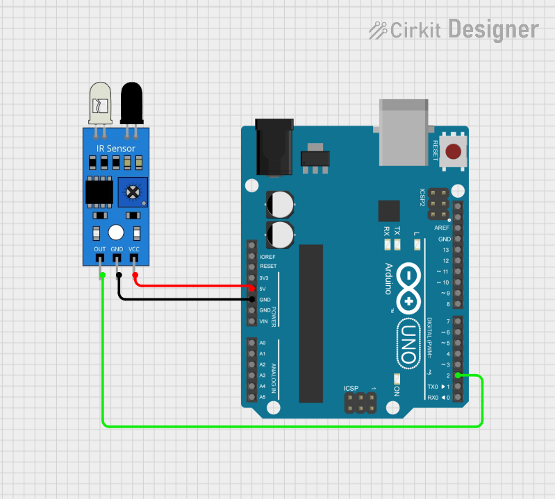
Below is an example of how to connect and use an IR sensor with an Arduino UNO:
Circuit Connections
- Connect the VCC pin of the IR sensor to the 5V pin on the Arduino.
- Connect the GND pin of the IR sensor to the GND pin on the Arduino.
- Connect the OUT pin of the IR sensor to digital pin 2 on the Arduino.
Arduino Code
// IR Sensor Example Code
// This code reads the digital output of an IR sensor and turns on an LED
// when an object is detected.

const int irSensorPin = 2;  // IR sensor output pin connected to digital pin 2
const int ledPin = 13;      // Built-in LED pin on Arduino

void setup() {
  pinMode(irSensorPin, INPUT);  // Set IR sensor pin as input
  pinMode(ledPin, OUTPUT);      // Set LED pin as output
  Serial.begin(9600);           // Initialize serial communication
}

void loop() {
  int sensorValue = digitalRead(irSensorPin);  // Read the IR sensor output

  if (sensorValue == HIGH) {
    // Object detected
    digitalWrite(ledPin, HIGH);  // Turn on the LED
    Serial.println("Object detected!");
  } else {
    // No object detected
    digitalWrite(ledPin, LOW);   // Turn off the LED
    Serial.println("No object detected.");
  }

  delay(100);  // Small delay for stability
}
Troubleshooting and FAQs
Common Issues
The sensor is not detecting objects.
- Ensure the sensor is powered correctly (check VCC and GND connections).
- Verify that the object is within the detection range.
- Adjust the sensitivity using the potentiometer (if available).
False detections or erratic behavior.
- Check for interference from ambient light or other IR sources.
- Ensure a stable power supply to the sensor.
- Verify that the sensor is not too close to reflective surfaces.
Output signal is not changing.
- Confirm that the output pin is connected to the correct microcontroller pin.
- Test the sensor with a multimeter to verify the output signal.
FAQs
Q: Can the IR sensor detect objects through glass?
A: It depends on the type of glass. Some glass materials block infrared radiation, while others allow it to pass through. Test the sensor with the specific glass material in your application.
Q: What is the maximum detection range of an IR sensor?
A: The detection range varies by model, typically between 2cm and 30cm. Check the datasheet of your specific sensor for exact details.
Q: Can I use an IR sensor outdoors?
A: Yes, but be aware that strong sunlight or other IR sources may interfere with the sensor's performance. Consider using an IR filter or shielding to improve reliability.
Q: How do I differentiate between multiple IR sensors in a circuit?
A: Assign each sensor to a separate input pin on your microcontroller and handle them individually in your code.