
How to Use shaft encoder: Examples, Pinouts, and Specs
 Design with shaft encoder in Cirkit Designer
Introduction
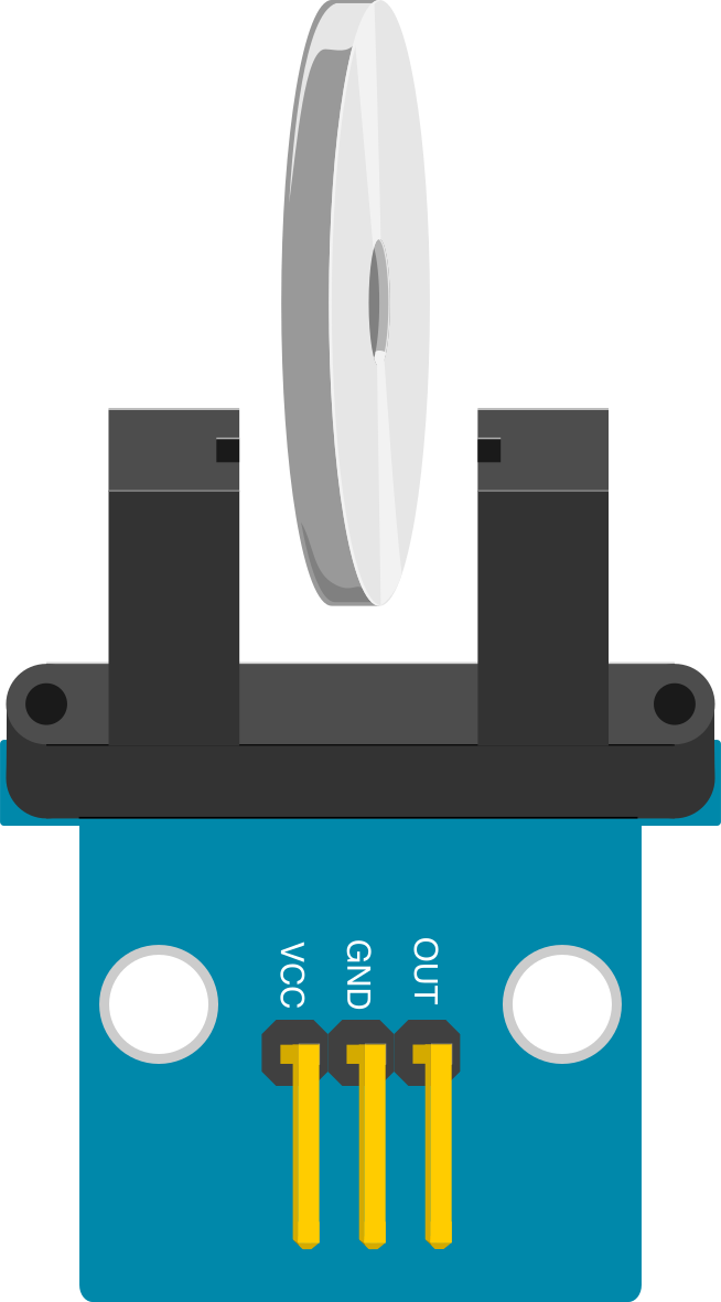
A shaft encoder is a device that converts the rotational position or motion of a shaft into an electrical signal. This signal can represent either the absolute position of the shaft (absolute encoder) or the relative motion (incremental encoder). Shaft encoders are widely used in control systems, robotics, industrial automation, and motor feedback applications. They provide precise feedback for position, speed, and direction, making them essential in systems requiring accurate motion control.
Explore Projects Built with shaft encoder
 Open Project in Cirkit Designer
 Open Project in Cirkit Designer
 Open Project in Cirkit Designer
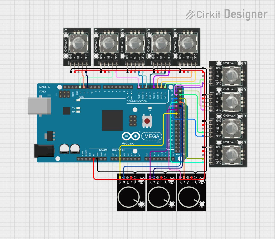 Open Project in Cirkit Designer
Explore Projects Built with shaft encoder
Open Project in Cirkit DesignerOpen Project in Cirkit DesignerOpen Project in Cirkit DesignerOpen Project in Cirkit DesignerCommon Applications
- Robotics for position and motion feedback
- CNC machines and 3D printers for precise control
- Industrial automation systems
- Motor speed and direction monitoring
- Elevators and conveyor systems
Technical Specifications
The specifications of a shaft encoder can vary depending on the type and model. Below are general specifications for a typical incremental rotary shaft encoder:
Key Technical Details
- Supply Voltage: 5V to 24V DC (model-dependent)
- Output Signal: Quadrature (A and B channels), optional Z (index) channel
- Resolution: 100 to 10,000 pulses per revolution (PPR)
- Maximum Rotational Speed: Up to 10,000 RPM
- Output Type: Open collector, push-pull, or differential
- Operating Temperature: -20°C to +85°C
- Shaft Diameter: 6mm to 12mm (varies by model)
Pin Configuration and Descriptions
Below is a typical pinout for a 5-pin incremental shaft encoder:
| Pin | Name | Description |
|---|---|---|
| 1 | VCC | Power supply input (5V to 24V DC) |
| 2 | GND | Ground connection |
| 3 | A | Channel A output signal |
| 4 | B | Channel B output signal (90° phase shift from A) |
| 5 | Z (optional) | Index pulse output (one pulse per revolution) |
Note: Always refer to the datasheet of your specific encoder model for exact pinout details.
Usage Instructions
How to Use the Shaft Encoder in a Circuit
- Power the Encoder: Connect the VCC pin to a regulated power supply (e.g., 5V or 12V) and the GND pin to the ground of your circuit.
- Connect Output Signals:
- Connect the A and B output pins to the input pins of a microcontroller or a decoder circuit.
- If using the Z channel, connect it to an additional input pin for index pulse detection.
- Read the Signals: Use a microcontroller to read the quadrature signals (A and B) to determine the direction and speed of rotation. The Z channel can be used to detect the start or end of a revolution.
Important Considerations
- Debouncing: Use hardware or software debouncing to filter out noise in the encoder signals.
- Pull-up Resistors: If the encoder outputs are open collector, use pull-up resistors on the A, B, and Z lines.
- Signal Interfacing: Ensure the encoder output voltage levels are compatible with your microcontroller or interface circuit.
- Mounting: Securely mount the encoder to the shaft to avoid misalignment or slippage.
Example: Using a Shaft Encoder with Arduino UNO
Below is an example of interfacing an incremental shaft encoder with an Arduino UNO to read position and direction:
// Define encoder pins
const int encoderPinA = 2; // Channel A connected to digital pin 2
const int encoderPinB = 3; // Channel B connected to digital pin 3

volatile int encoderPosition = 0; // Variable to store encoder position
int lastEncoded = 0; // Variable to store the last encoder state

void setup() {
  pinMode(encoderPinA, INPUT_PULLUP); // Set pin A as input with pull-up
  pinMode(encoderPinB, INPUT_PULLUP); // Set pin B as input with pull-up

  // Attach interrupts to encoder pins
  attachInterrupt(digitalPinToInterrupt(encoderPinA), updateEncoder, CHANGE);
  attachInterrupt(digitalPinToInterrupt(encoderPinB), updateEncoder, CHANGE);

  Serial.begin(9600); // Initialize serial communication
}

void loop() {
  // Print the encoder position
  Serial.print("Encoder Position: ");
  Serial.println(encoderPosition);
  delay(100); // Delay for readability
}

void updateEncoder() {
  // Read the current state of the encoder pins
  int MSB = digitalRead(encoderPinA); // Most significant bit
  int LSB = digitalRead(encoderPinB); // Least significant bit

  int encoded = (MSB << 1) | LSB; // Combine the two bits
  int sum = (lastEncoded << 2) | encoded; // Combine with previous state

  // Determine direction based on state transitions
  if (sum == 0b1101 || sum == 0b0100 || sum == 0b0010 || sum == 0b1011) {
    encoderPosition++; // Clockwise rotation
  } else if (sum == 0b1110 || sum == 0b0111 || sum == 0b0001 || sum == 0b1000) {
    encoderPosition--; // Counterclockwise rotation
  }

  lastEncoded = encoded; // Update the last state
}
Note: Ensure the encoder is connected to interrupt-capable pins on the Arduino (e.g., pins 2 and 3 on the UNO).
Troubleshooting and FAQs
Common Issues
- No Signal Output:
- Check the power supply voltage and connections.
- Verify the encoder is properly mounted to the shaft.
- Incorrect Position or Direction:
- Ensure the A and B channels are connected to the correct pins.
- Verify the software logic for decoding quadrature signals.
- Noisy or Unstable Readings:
- Add hardware or software debouncing to filter out noise.
- Use shielded cables for long connections to reduce interference.
FAQs
Q: Can I use a shaft encoder with a Raspberry Pi?
A: Yes, but ensure you use GPIO pins capable of handling high-speed signals. You may also need external circuitry for signal conditioning.
Q: What is the difference between absolute and incremental encoders?
A: Absolute encoders provide the exact position of the shaft, while incremental encoders provide relative motion information.
Q: How do I calculate the speed of rotation?
A: Measure the time between pulses on the A or B channel and use the encoder's PPR value to calculate the speed.
By following this documentation, you can effectively integrate a shaft encoder into your projects for precise motion control and feedback.