Cirkit Designer Logo
Cirkit Designer
Your all-in-one circuit design IDE
Home / 
Component Documentation

How to Use CH9329: Examples, Pinouts, and Specs

Image of CH9329
Cirkit Designer LogoDesign with CH9329 in Cirkit Designer

Introduction

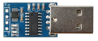
The CH9329 is a USB to UART bridge controller designed to facilitate seamless communication between USB devices and UART (Universal Asynchronous Receiver-Transmitter) interfaces. It acts as a bridge, converting USB signals to UART signals and vice versa, enabling serial communication in embedded systems. The CH9329 supports a wide range of baud rates, making it versatile for various applications.

Explore Projects Built with CH9329

Use Cirkit Designer to design, explore, and prototype these projects online. Some projects support real-time simulation. Click "Open Project" to start designing instantly!
Configurable Battery-Powered RF Signal Transmitter with DIP Switch Settings
Image of fyp transmitter: A project utilizing CH9329 in a practical application
This circuit appears to be a configurable encoder system with an RF transmission capability. The encoder's address pins (A0-A7) are connected to a DIP switch for setting the address, and its data output (DO) is connected to an RF transmitter, allowing the encoded signal to be wirelessly transmitted. The circuit is powered by a 9V battery, regulated to 5V by a 7805 voltage regulator, and includes a diode for polarity protection. Tactile switches are connected to the encoder's data inputs (D1-D3), and an LED with a current-limiting resistor indicates power or activity.
Cirkit Designer LogoOpen Project in Cirkit Designer
Battery-Powered Emergency Alert System with NUCLEO-F072RB, SIM800L, and GPS NEO 6M
Image of women safety: A project utilizing CH9329 in a practical application
This circuit is an emergency alert system that uses a NUCLEO-F072RB microcontroller to send SMS alerts and make calls via a SIM800L GSM module, while obtaining location data from a GPS NEO 6M module. The system is powered by a Li-ion battery and includes a TP4056 module for battery charging and protection, with a rocker switch to control power to the microcontroller.
Cirkit Designer LogoOpen Project in Cirkit Designer
Battery-Powered LED and Buzzer Control Circuit Using BC547 Transistors
Image of Water level Indicator : A project utilizing CH9329 in a practical application
This circuit is a multi-indicator system powered by a 9V battery, utilizing three BC547 transistors to control three LEDs (red, green, and yellow) and a buzzer. Each transistor is configured to switch its respective LED and the buzzer on and off, likely based on external signals connected via alligator clips.
Cirkit Designer LogoOpen Project in Cirkit Designer
ESP32-Controlled Multi-Display Interactive System with Pushbutton Inputs
Image of ORBS: A project utilizing CH9329 in a practical application
This circuit consists of multiple GC9A01 display modules interfaced with an ESP32 microcontroller. The ESP32 controls the reset (RST), chip select (CS), data/command (DC), serial data (SDA), and serial clock (SCL) lines of each display, allowing for individual communication with each screen. Additionally, there are pushbuttons connected to the ESP32, which could be used for user input to control the displays or other functions within the circuit.
Cirkit Designer LogoOpen Project in Cirkit Designer

Explore Projects Built with CH9329

Use Cirkit Designer to design, explore, and prototype these projects online. Some projects support real-time simulation. Click "Open Project" to start designing instantly!
Image of fyp transmitter: A project utilizing CH9329 in a practical application
Configurable Battery-Powered RF Signal Transmitter with DIP Switch Settings
This circuit appears to be a configurable encoder system with an RF transmission capability. The encoder's address pins (A0-A7) are connected to a DIP switch for setting the address, and its data output (DO) is connected to an RF transmitter, allowing the encoded signal to be wirelessly transmitted. The circuit is powered by a 9V battery, regulated to 5V by a 7805 voltage regulator, and includes a diode for polarity protection. Tactile switches are connected to the encoder's data inputs (D1-D3), and an LED with a current-limiting resistor indicates power or activity.
Cirkit Designer LogoOpen Project in Cirkit Designer
Image of women safety: A project utilizing CH9329 in a practical application
Battery-Powered Emergency Alert System with NUCLEO-F072RB, SIM800L, and GPS NEO 6M
This circuit is an emergency alert system that uses a NUCLEO-F072RB microcontroller to send SMS alerts and make calls via a SIM800L GSM module, while obtaining location data from a GPS NEO 6M module. The system is powered by a Li-ion battery and includes a TP4056 module for battery charging and protection, with a rocker switch to control power to the microcontroller.
Cirkit Designer LogoOpen Project in Cirkit Designer
Image of Water level Indicator : A project utilizing CH9329 in a practical application
Battery-Powered LED and Buzzer Control Circuit Using BC547 Transistors
This circuit is a multi-indicator system powered by a 9V battery, utilizing three BC547 transistors to control three LEDs (red, green, and yellow) and a buzzer. Each transistor is configured to switch its respective LED and the buzzer on and off, likely based on external signals connected via alligator clips.
Cirkit Designer LogoOpen Project in Cirkit Designer
Image of ORBS: A project utilizing CH9329 in a practical application
ESP32-Controlled Multi-Display Interactive System with Pushbutton Inputs
This circuit consists of multiple GC9A01 display modules interfaced with an ESP32 microcontroller. The ESP32 controls the reset (RST), chip select (CS), data/command (DC), serial data (SDA), and serial clock (SCL) lines of each display, allowing for individual communication with each screen. Additionally, there are pushbuttons connected to the ESP32, which could be used for user input to control the displays or other functions within the circuit.
Cirkit Designer LogoOpen Project in Cirkit Designer

Common Applications and Use Cases

  • USB-to-serial communication in embedded systems
  • Debugging and programming microcontrollers
  • Data transfer between computers and UART-enabled devices
  • Industrial automation and control systems
  • USB-based serial adapters and converters

Technical Specifications

The CH9329 is a highly reliable and efficient component with the following key specifications:

Key Technical Details

  • USB Interface: USB 2.0 Full-Speed compliant
  • UART Interface: Supports baud rates from 1200 bps to 115200 bps
  • Operating Voltage: 3.3V to 5V
  • Operating Temperature: -40°C to +85°C
  • Power Consumption: Low power consumption in active and idle modes
  • Driver Support: Compatible with Windows, Linux, and macOS
  • Package Type: SOP-16 or QFN-16

Pin Configuration and Descriptions

The CH9329 is typically available in a 16-pin package. Below is the pin configuration and description:

Pin Number Pin Name Description
1 VCC Power supply input (3.3V to 5V)
2 GND Ground
3 TXD UART Transmit Data
4 RXD UART Receive Data
5 RTS Request to Send (flow control, optional)
6 CTS Clear to Send (flow control, optional)
7 DTR Data Terminal Ready (optional)
8 DSR Data Set Ready (optional)
9 USB_DM USB Data Minus
10 USB_DP USB Data Plus
11 RESET Reset input (active low)
12 NC No connection
13 NC No connection
14 NC No connection
15 NC No connection
16 NC No connection

Usage Instructions

The CH9329 is straightforward to use in a circuit. Below are the steps and best practices for integrating it into your design:

How to Use the CH9329 in a Circuit

  1. Power Supply: Connect the VCC pin to a 3.3V or 5V power source and the GND pin to ground.
  2. USB Connection: Connect the USB_DM and USB_DP pins to the USB data lines of your device.
  3. UART Connection: Connect the TXD and RXD pins to the UART interface of your microcontroller or device.
  4. Optional Flow Control: If required, connect the RTS and CTS pins for hardware flow control.
  5. Reset: Use the RESET pin to initialize the CH9329. Pull it low momentarily to reset the device.

Important Considerations and Best Practices

  • Ensure proper decoupling capacitors are placed near the VCC pin to stabilize the power supply.
  • Use appropriate pull-up resistors on the USB_DP and USB_DM lines if required by your USB host.
  • Verify the baud rate settings on both the CH9329 and the UART device to ensure proper communication.
  • Avoid long traces for the USB and UART lines to minimize signal degradation.
  • If connecting to an Arduino UNO, use the SoftwareSerial library to communicate with the CH9329.

Example Code for Arduino UNO

Below is an example of how to use the CH9329 with an Arduino UNO for serial communication:

#include <SoftwareSerial.h>

// Define RX and TX pins for SoftwareSerial
SoftwareSerial mySerial(10, 11); // RX = pin 10, TX = pin 11

void setup() {
  // Start the hardware serial communication (USB to PC)
  Serial.begin(9600);
  // Start the software serial communication (to CH9329)
  mySerial.begin(9600);

  Serial.println("CH9329 Communication Initialized");
}

void loop() {
  // Check if data is available from the CH9329
  if (mySerial.available()) {
    // Read data from CH9329 and send it to the Serial Monitor
    char data = mySerial.read();
    Serial.print("Received: ");
    Serial.println(data);
  }

  // Check if data is available from the Serial Monitor
  if (Serial.available()) {
    // Read data from Serial Monitor and send it to the CH9329
    char data = Serial.read();
    mySerial.write(data);
    Serial.print("Sent: ");
    Serial.println(data);
  }
}

Troubleshooting and FAQs

Common Issues and Solutions

  1. No Communication Between USB and UART

    • Cause: Incorrect baud rate settings.
    • Solution: Ensure the baud rate of the CH9329 matches the UART device.
  2. Device Not Recognized by USB Host

    • Cause: Missing or incorrect USB drivers.
    • Solution: Install the appropriate drivers for your operating system.
  3. Data Corruption or Loss

    • Cause: Signal degradation or noise on the UART lines.
    • Solution: Use shorter traces and proper shielding for UART connections.
  4. CH9329 Not Responding

    • Cause: Improper power supply or reset configuration.
    • Solution: Verify the power supply voltage and ensure the RESET pin is properly connected.

FAQs

Q1: Can the CH9329 support higher baud rates?
A1: The CH9329 supports baud rates up to 115200 bps. For higher baud rates, consider alternative USB-to-UART bridge controllers.

Q2: Is the CH9329 compatible with 1.8V logic levels?
A2: No, the CH9329 operates at 3.3V or 5V logic levels. Use a level shifter if interfacing with 1.8V devices.

Q3: Do I need external crystal oscillators for the CH9329?
A3: No, the CH9329 has an internal oscillator and does not require an external crystal.

Q4: Can I use the CH9329 with a Raspberry Pi?
A4: Yes, the CH9329 can be connected to the UART pins of a Raspberry Pi for serial communication.

By following this documentation, you can effectively integrate the CH9329 into your projects and troubleshoot common issues.