Cirkit Designer Logo
Cirkit Designer
Your all-in-one circuit design IDE
Home / 
Component Documentation

How to Use battery level 2S: Examples, Pinouts, and Specs

Image of battery level 2S
Cirkit Designer LogoDesign with battery level 2S in Cirkit Designer

Introduction

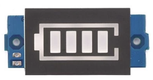
The Battery Level 2S (Manufacturer: Pin, Part ID: 003) is a monitoring module designed for 2S lithium-ion battery packs. A 2S battery consists of two lithium-ion cells connected in series, providing a nominal voltage of 7.4V. This component is ideal for applications requiring precise battery level monitoring, such as RC vehicles, drones, and portable electronics. Its lightweight and compact design make it a popular choice for energy-dense systems.

Explore Projects Built with battery level 2S

Use Cirkit Designer to design, explore, and prototype these projects online. Some projects support real-time simulation. Click "Open Project" to start designing instantly!
Battery-Powered Servo Control System with 2S 30A BMS and TP5100 Charger
Image of servo power supply: A project utilizing battery level 2S in a practical application
This circuit is a battery management and charging system for a 2S lithium-ion battery pack, which powers multiple MG996R servos. The TP5100 module charges the battery pack from a 12V power supply, while the 2S 30A BMS ensures safe operation and distribution of power to the servos.
Cirkit Designer LogoOpen Project in Cirkit Designer
Battery-Powered Adjustable Voltage Regulator with Li-ion 18650 Batteries and BMS
Image of mini ups: A project utilizing battery level 2S in a practical application
This circuit is a power management system that uses four Li-ion 18650 batteries connected to a 2S 30A BMS for battery management and protection. The system includes step-up and step-down voltage regulators to provide adjustable output voltages, controlled by a rocker switch, and multiple DC jacks for power input and output.
Cirkit Designer LogoOpen Project in Cirkit Designer
Battery-Powered 18650 Li-ion Charger with USB Output and Adjustable Voltage Regulator
Image of Breadboard: A project utilizing battery level 2S in a practical application
This circuit is a battery management and power supply system that uses three 3.7V batteries connected to a 3S 10A Li-ion 18650 Charger Protection Board Module for balanced charging and protection. The system includes a TP4056 Battery Charging Protection Module for additional charging safety, a Step Up Boost Power Converter to regulate and boost the voltage, and a USB regulator to provide a stable 5V output, controlled by a push switch.
Cirkit Designer LogoOpen Project in Cirkit Designer
18650 Li-ion Battery Pack with BMS for 5V Power Supply
Image of battary: A project utilizing battery level 2S in a practical application
This circuit consists of a battery management system (BMS) connected to a series of 18650 Li-ion batteries arranged in a 4S configuration to provide a regulated output voltage. The BMS ensures safe charging and discharging of the batteries, while a connector provides a 5V output for external devices.
Cirkit Designer LogoOpen Project in Cirkit Designer

Explore Projects Built with battery level 2S

Use Cirkit Designer to design, explore, and prototype these projects online. Some projects support real-time simulation. Click "Open Project" to start designing instantly!
Image of servo power supply: A project utilizing battery level 2S in a practical application
Battery-Powered Servo Control System with 2S 30A BMS and TP5100 Charger
This circuit is a battery management and charging system for a 2S lithium-ion battery pack, which powers multiple MG996R servos. The TP5100 module charges the battery pack from a 12V power supply, while the 2S 30A BMS ensures safe operation and distribution of power to the servos.
Cirkit Designer LogoOpen Project in Cirkit Designer
Image of mini ups: A project utilizing battery level 2S in a practical application
Battery-Powered Adjustable Voltage Regulator with Li-ion 18650 Batteries and BMS
This circuit is a power management system that uses four Li-ion 18650 batteries connected to a 2S 30A BMS for battery management and protection. The system includes step-up and step-down voltage regulators to provide adjustable output voltages, controlled by a rocker switch, and multiple DC jacks for power input and output.
Cirkit Designer LogoOpen Project in Cirkit Designer
Image of Breadboard: A project utilizing battery level 2S in a practical application
Battery-Powered 18650 Li-ion Charger with USB Output and Adjustable Voltage Regulator
This circuit is a battery management and power supply system that uses three 3.7V batteries connected to a 3S 10A Li-ion 18650 Charger Protection Board Module for balanced charging and protection. The system includes a TP4056 Battery Charging Protection Module for additional charging safety, a Step Up Boost Power Converter to regulate and boost the voltage, and a USB regulator to provide a stable 5V output, controlled by a push switch.
Cirkit Designer LogoOpen Project in Cirkit Designer
Image of battary: A project utilizing battery level 2S in a practical application
18650 Li-ion Battery Pack with BMS for 5V Power Supply
This circuit consists of a battery management system (BMS) connected to a series of 18650 Li-ion batteries arranged in a 4S configuration to provide a regulated output voltage. The BMS ensures safe charging and discharging of the batteries, while a connector provides a 5V output for external devices.
Cirkit Designer LogoOpen Project in Cirkit Designer

Common Applications

  • Remote-controlled (RC) vehicles and drones
  • Portable electronic devices
  • Robotics and IoT systems
  • Backup power supplies

Technical Specifications

Key Technical Details

Parameter Value
Nominal Voltage 7.4V (2S lithium-ion battery)
Input Voltage Range 6.0V - 8.4V
Output Signal Analog or digital (varies by model)
Operating Temperature -20°C to 60°C
Dimensions 25mm x 15mm x 5mm
Weight 5 grams

Pin Configuration and Descriptions

Pin Number Pin Name Description
1 V+ Positive terminal of the 2S battery input
2 V- Negative terminal of the 2S battery input
3 OUT Battery level output signal (analog or digital)
4 GND Ground connection

Usage Instructions

How to Use the Component in a Circuit

  1. Connect the Battery:
    • Attach the positive terminal of the 2S battery to the V+ pin.
    • Attach the negative terminal of the 2S battery to the V- pin.
  2. Connect the Output:
    • For analog output, connect the OUT pin to an analog input pin of your microcontroller.
    • For digital output, connect the OUT pin to a digital input pin.
  3. Ground Connection:
    • Ensure the GND pin is connected to the ground of your circuit.

Important Considerations and Best Practices

  • Voltage Range: Ensure the battery voltage remains within the specified range (6.0V - 8.4V) to avoid damage to the component.
  • Polarity: Double-check the polarity of the connections to prevent short circuits or damage.
  • Calibration: If using the analog output, calibrate the microcontroller's ADC (Analog-to-Digital Converter) to interpret the voltage levels accurately.
  • Heat Management: Avoid exposing the component to temperatures beyond its operating range (-20°C to 60°C).

Example Code for Arduino UNO

Below is an example of how to read the battery level using the analog output of the Battery Level 2S module:

// Define the analog pin connected to the OUT pin of the Battery Level 2S
const int batteryPin = A0;

// Variable to store the battery voltage
float batteryVoltage;

void setup() {
  // Initialize serial communication for debugging
  Serial.begin(9600);
}

void loop() {
  // Read the analog value from the battery level module
  int analogValue = analogRead(batteryPin);

  // Convert the analog value to voltage (assuming 5V reference and 10-bit ADC)
  batteryVoltage = (analogValue / 1023.0) * 5.0;

  // Scale the voltage to match the 2S battery range (6.0V - 8.4V)
  batteryVoltage = batteryVoltage * (8.4 / 5.0);

  // Print the battery voltage to the Serial Monitor
  Serial.print("Battery Voltage: ");
  Serial.print(batteryVoltage);
  Serial.println(" V");

  // Add a delay for stability
  delay(1000);
}

Troubleshooting and FAQs

Common Issues and Solutions

  1. No Output Signal:

    • Cause: Incorrect wiring or loose connections.
    • Solution: Verify all connections, ensuring proper polarity and secure contacts.
  2. Inaccurate Voltage Readings:

    • Cause: ADC calibration mismatch or noise in the circuit.
    • Solution: Calibrate the ADC of your microcontroller and use decoupling capacitors to reduce noise.
  3. Overheating:

    • Cause: Operating outside the specified voltage or temperature range.
    • Solution: Ensure the battery voltage is within 6.0V - 8.4V and maintain ambient temperatures within -20°C to 60°C.
  4. Module Not Responding:

    • Cause: Damaged module due to reverse polarity or overvoltage.
    • Solution: Replace the module and ensure proper wiring in future setups.

FAQs

Q1: Can this module be used with a 3S battery?
A1: No, the Battery Level 2S is specifically designed for 2S lithium-ion batteries. Using it with a 3S battery may damage the module.

Q2: How do I interpret the analog output?
A2: The analog output corresponds to the battery voltage. Use the provided formula in the example code to scale the readings to the 2S battery range.

Q3: Is the module compatible with Arduino Nano?
A3: Yes, the module is compatible with Arduino Nano and other microcontrollers with analog or digital input pins.

Q4: Can I use this module for lithium-polymer (LiPo) batteries?
A4: Yes, as long as the LiPo battery is a 2S configuration with a nominal voltage of 7.4V.