How to Use Arduino UNO: Examples, Pinouts, and Specs
Introduction
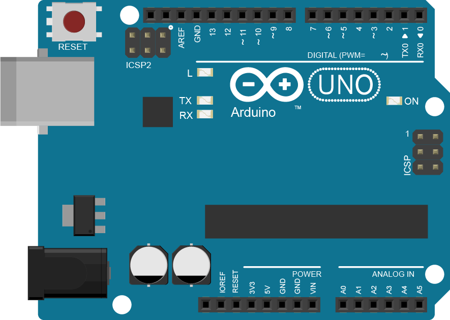
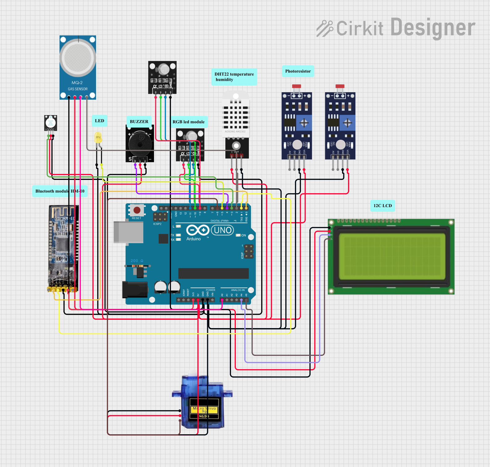
The Arduino UNO is a versatile and user-friendly microcontroller board based on the ATmega328P microcontroller. It is an integral part of the Arduino platform, which provides an accessible way for hobbyists, artists, and engineers to create interactive projects. With its array of digital and analog I/O pins, the Arduino UNO can interface with a wide range of sensors, actuators, and shields, making it suitable for countless applications from robotics to home automation.
Explore Projects Built with Arduino UNO
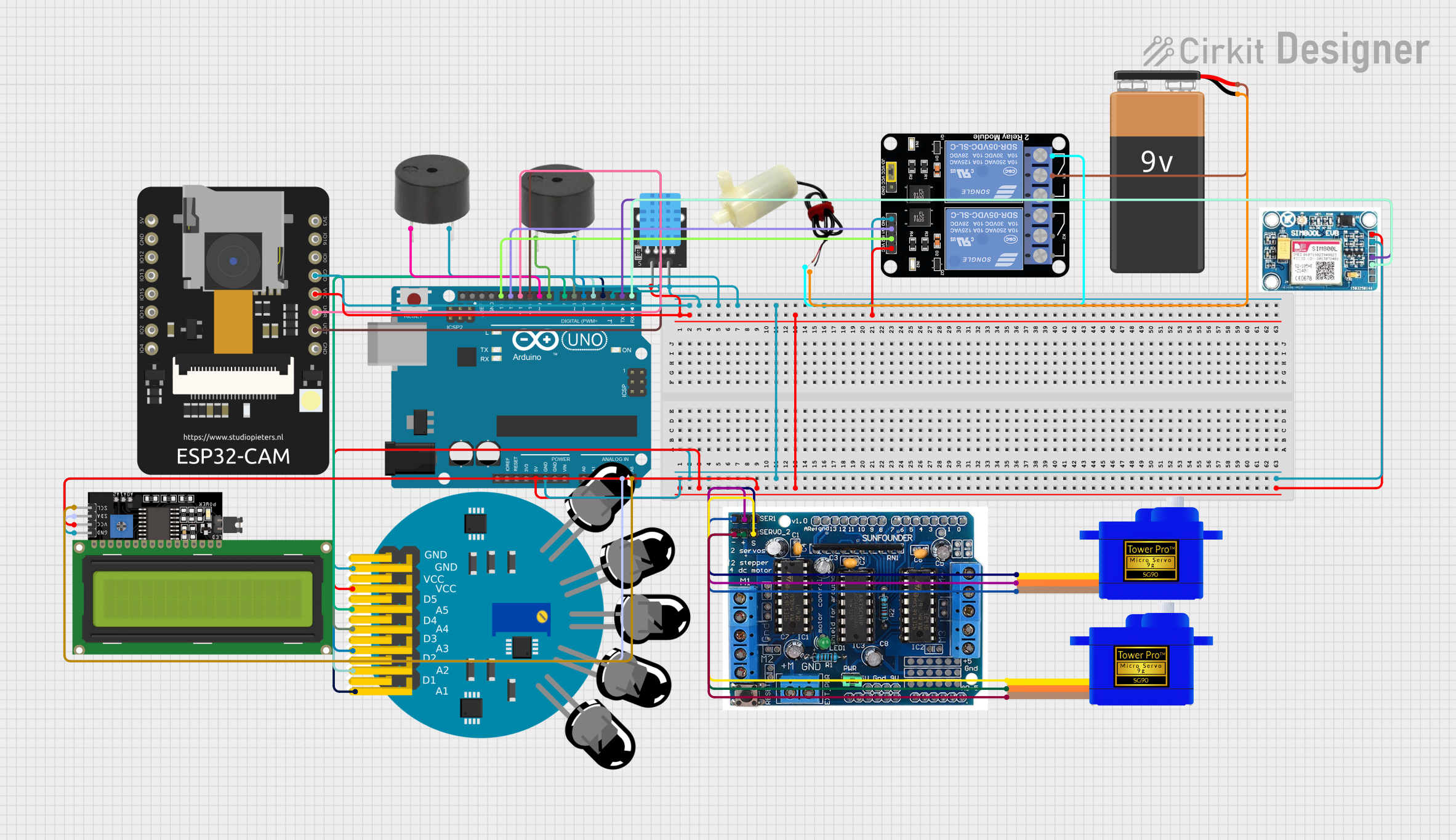
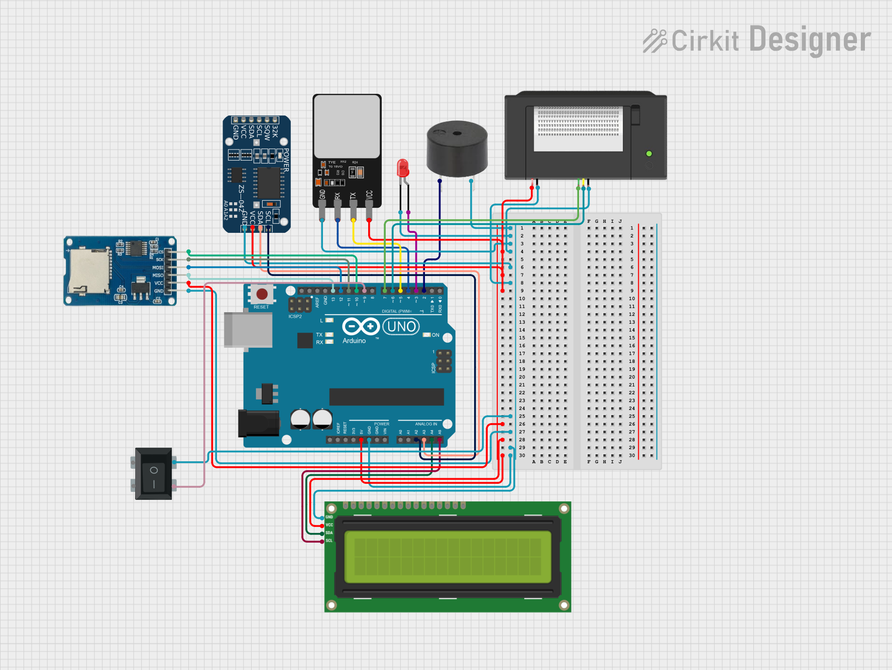
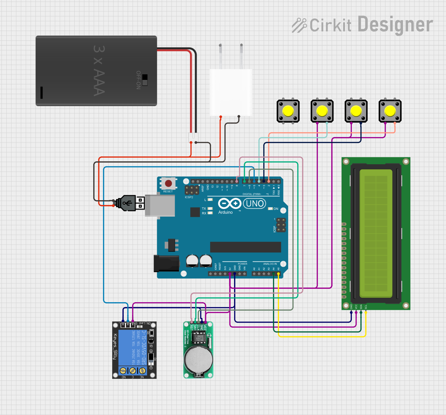
Explore Projects Built with Arduino UNO
Technical Specifications
Key Technical Details
- Microcontroller: ATmega328P
- Operating Voltage: 5V
- Input Voltage (recommended): 7-12V
- Input Voltage (limit): 6-20V
- Digital I/O Pins: 14 (of which 6 provide PWM output)
- Analog Input Pins: 6
- DC Current per I/O Pin: 20 mA
- DC Current for 3.3V Pin: 50 mA
- Flash Memory: 32 KB (ATmega328P) of which 0.5 KB used by bootloader
- SRAM: 2 KB (ATmega328P)
- EEPROM: 1 KB (ATmega328P)
- Clock Speed: 16 MHz
- LED_BUILTIN: Pin 13
Pin Configuration and Descriptions
| Pin Number | Function | Description |
|---|---|---|
| 0 | RX | Digital pin used for serial communication (RX). |
| 1 | TX | Digital pin used for serial communication (TX). |
| 2-13 | Digital I/O | Digital pins for input/output. Pins 3,5,6,9,10,11 are PWM. |
| A0-A5 | Analog Input | Analog input pins. |
| AREF | Analog Reference | Reference voltage for the analog inputs. |
| GND | Ground | Ground pins. |
| RST | Reset | Used to reset the microcontroller. |
| 3V3 | 3.3V Supply | Provides 3.3V output (50 mA max). |
| 5V | 5V Supply | Provides 5V output (drawn from USB or VIN). |
| VIN | Input Voltage | Used to power the board with an external power source. |
Usage Instructions
Setting Up the Arduino UNO
- Connect the Arduino UNO to your computer using a USB cable.
- Install the Arduino IDE from the official Arduino website.
- Select the correct board and port in the Arduino IDE.
- Write or upload your sketch (program) to the board.
Best Practices
- Always disconnect the Arduino UNO from power sources before making or altering connections.
- Avoid supplying voltage higher than the recommended limit to any I/O pin.
- Use external power supplies when connecting components that draw more current than the board can provide.
- Utilize the onboard LED connected to pin 13 for debugging purposes.
Example Code
Here is a simple example of blinking the onboard LED:
// Define the LED_BUILTIN pin as a constant to improve readability
const int ledPin = LED_BUILTIN;

void setup() {
  // Initialize the digital pin as an output.
  pinMode(ledPin, OUTPUT);
}

void loop() {
  digitalWrite(ledPin, HIGH);   // Turn the LED on
  delay(1000);                  // Wait for a second
  digitalWrite(ledPin, LOW);    // Turn the LED off
  delay(1000);                  // Wait for a second
}
Troubleshooting and FAQs
Common Issues
The Arduino UNO is not recognized by the computer:
- Ensure the USB cable is properly connected and functional.
- Check that the correct drivers are installed.
- Try a different USB port or cable.
Sketch not uploading:
- Verify that the correct board and port are selected in the Arduino IDE.
- Ensure the board is not in use by another program.
- Check for error messages in the IDE console for specific issues.
Unexpected behavior in circuits:
- Double-check wiring and connections.
- Ensure power supply is adequate and within recommended limits.
- Review the code for logical errors or incorrect pin assignments.
FAQs
Can I power the Arduino UNO with a battery?
- Yes, you can use a battery connected to the VIN pin or the power jack, keeping in mind the voltage limits.
How do I reset the Arduino UNO?
- You can press the reset button on the board or use the RST pin.
What is the maximum current the Arduino UNO can supply?
- The 5V pin can supply a maximum of 400 mA or 500 mA, depending on the USB or external power supply used. The 3.3V pin can supply a maximum of 50 mA.
For more detailed troubleshooting, refer to the Arduino forums and the extensive community resources available online.