Cirkit Designer Logo
Cirkit Designer
Your all-in-one circuit design IDE
Home / 
Component Documentation

How to Use APR33A3: Examples, Pinouts, and Specs

Image of APR33A3
Cirkit Designer LogoDesign with APR33A3 in Cirkit Designer

Introduction

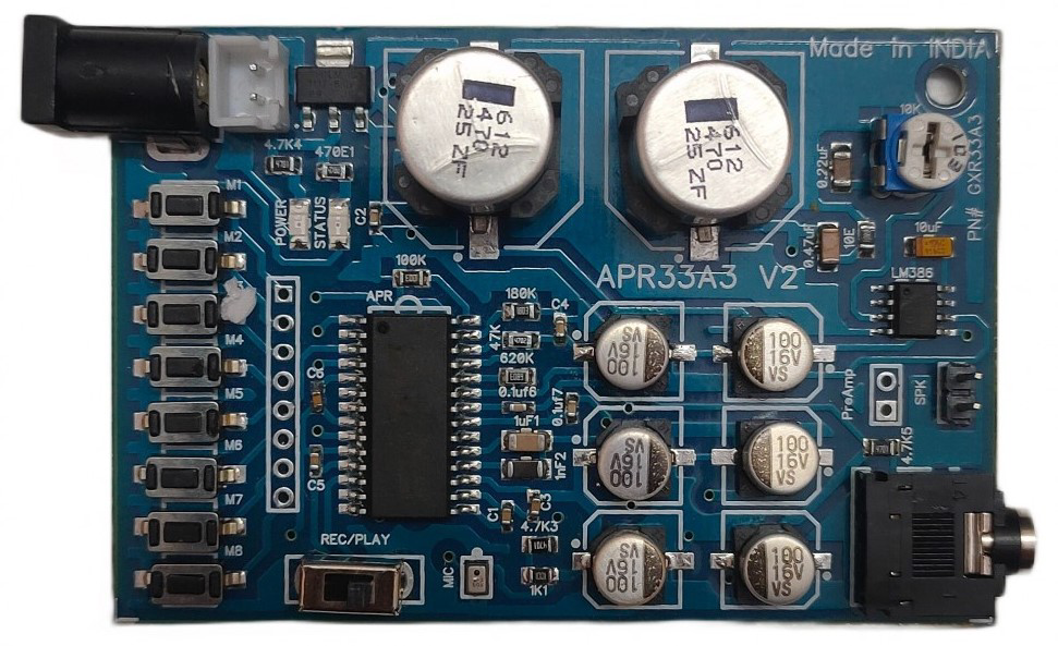
The APR33A3 is a high-performance voice recording and playback integrated circuit (IC) capable of storing up to 11 minutes of audio. This versatile component is widely used in various applications, including toys, alarms, and voice guidance systems. Its ease of use and robust performance make it a popular choice for both hobbyists and professionals.

Explore Projects Built with APR33A3

Use Cirkit Designer to design, explore, and prototype these projects online. Some projects support real-time simulation. Click "Open Project" to start designing instantly!
NFC-Enabled Access Control System with Time Logging
Image of doorlock: A project utilizing APR33A3 in a practical application
This circuit is designed for access control with time tracking capabilities. It features an NFC/RFID reader for authentication, an RTC module (DS3231) for real-time clock functionality, and an OLED display for user interaction. A 12V relay controls a magnetic lock, which is activated upon successful NFC/RFID authentication, and a button switch is likely used for manual operation or input. The T8_S3 microcontroller serves as the central processing unit, interfacing with the NFC/RFID reader, RTC, OLED, and relay to manage the access control logic.
Cirkit Designer LogoOpen Project in Cirkit Designer
Bioamplifier-Integrated ESP32 & Arduino UNO Wi-Fi Controlled Biometric Data Acquisition System
Image of epsilon: A project utilizing APR33A3 in a practical application
This circuit features an Arduino Nano ESP32 connected to a BioAmplifier (bioampexgpill) for biometric signal acquisition, with the amplifier's output connected to the Arduino's analog input (A0). The ESP32 is powered by a 3.7V LiPo battery, and the circuit also includes an Arduino UNO R4 WiFi connected to a servo motor and an LED, with the servo controlled via digital pin D6 and the LED connected to digital pin D12. The UNO is powered by a 9V battery, and the servo's power is supplied from the UNO's 5V output.
Cirkit Designer LogoOpen Project in Cirkit Designer
Satellite-Based Timing and Navigation System with SDR and Atomic Clock Synchronization
Image of GPS 시스템 측정 구성도_Confirm: A project utilizing APR33A3 in a practical application
This circuit appears to be a complex system involving power supply management, GPS and timing synchronization, and data communication. It includes a SI-TEX G1 Satellite Compass for GPS data, an XHTF1021 Atomic Rubidium Clock for precise timing, and Ettus USRP B200 units for software-defined radio communication. Power is supplied through various SMPS units and distributed via terminal blocks and DC jacks. Data communication is facilitated by Beelink MINI S12 N95 computers, RS232 splitters, and a 1000BASE-T Media Converter for network connectivity. RF Directional Couplers are used to interface antennas with the USRP units, and the entire system is likely contained within cases for protection and organization.
Cirkit Designer LogoOpen Project in Cirkit Designer
ESP32-Based Smart Sensor System with Wi-Fi and GPS Integration
Image of smart helmet: A project utilizing APR33A3 in a practical application
This circuit is an IoT-based sensor system using an ESP32 microcontroller to monitor alcohol levels, motion, and IR signals. It integrates an MQ-3 alcohol sensor, an MPU6050 accelerometer and gyroscope, an IR sensor, and a SIM808 GSM GPS module to collect data and send it to a cloud server for further analysis. The system also includes an LED indicator controlled by the ESP32.
Cirkit Designer LogoOpen Project in Cirkit Designer

Explore Projects Built with APR33A3

Use Cirkit Designer to design, explore, and prototype these projects online. Some projects support real-time simulation. Click "Open Project" to start designing instantly!
Image of doorlock: A project utilizing APR33A3 in a practical application
NFC-Enabled Access Control System with Time Logging
This circuit is designed for access control with time tracking capabilities. It features an NFC/RFID reader for authentication, an RTC module (DS3231) for real-time clock functionality, and an OLED display for user interaction. A 12V relay controls a magnetic lock, which is activated upon successful NFC/RFID authentication, and a button switch is likely used for manual operation or input. The T8_S3 microcontroller serves as the central processing unit, interfacing with the NFC/RFID reader, RTC, OLED, and relay to manage the access control logic.
Cirkit Designer LogoOpen Project in Cirkit Designer
Image of epsilon: A project utilizing APR33A3 in a practical application
Bioamplifier-Integrated ESP32 & Arduino UNO Wi-Fi Controlled Biometric Data Acquisition System
This circuit features an Arduino Nano ESP32 connected to a BioAmplifier (bioampexgpill) for biometric signal acquisition, with the amplifier's output connected to the Arduino's analog input (A0). The ESP32 is powered by a 3.7V LiPo battery, and the circuit also includes an Arduino UNO R4 WiFi connected to a servo motor and an LED, with the servo controlled via digital pin D6 and the LED connected to digital pin D12. The UNO is powered by a 9V battery, and the servo's power is supplied from the UNO's 5V output.
Cirkit Designer LogoOpen Project in Cirkit Designer
Image of GPS 시스템 측정 구성도_Confirm: A project utilizing APR33A3 in a practical application
Satellite-Based Timing and Navigation System with SDR and Atomic Clock Synchronization
This circuit appears to be a complex system involving power supply management, GPS and timing synchronization, and data communication. It includes a SI-TEX G1 Satellite Compass for GPS data, an XHTF1021 Atomic Rubidium Clock for precise timing, and Ettus USRP B200 units for software-defined radio communication. Power is supplied through various SMPS units and distributed via terminal blocks and DC jacks. Data communication is facilitated by Beelink MINI S12 N95 computers, RS232 splitters, and a 1000BASE-T Media Converter for network connectivity. RF Directional Couplers are used to interface antennas with the USRP units, and the entire system is likely contained within cases for protection and organization.
Cirkit Designer LogoOpen Project in Cirkit Designer
Image of smart helmet: A project utilizing APR33A3 in a practical application
ESP32-Based Smart Sensor System with Wi-Fi and GPS Integration
This circuit is an IoT-based sensor system using an ESP32 microcontroller to monitor alcohol levels, motion, and IR signals. It integrates an MQ-3 alcohol sensor, an MPU6050 accelerometer and gyroscope, an IR sensor, and a SIM808 GSM GPS module to collect data and send it to a cloud server for further analysis. The system also includes an LED indicator controlled by the ESP32.
Cirkit Designer LogoOpen Project in Cirkit Designer

Technical Specifications

Key Technical Details

Parameter Value
Operating Voltage 2.4V to 6.5V
Current Consumption 25mA (recording), 15mA (playback)
Audio Storage Time Up to 11 minutes
Sampling Rate 8kHz
Audio Quality 8-bit resolution
Interface SPI
Package 28-pin SOP

Pin Configuration and Descriptions

Pin No. Pin Name Description
1 VCC Power Supply (2.4V to 6.5V)
2 GND Ground
3 REC Record Control Input
4 PLAYE Edge-activated Playback Control Input
5 PLAYL Level-activated Playback Control Input
6 MIC+ Microphone Positive Input
7 MIC- Microphone Negative Input
8 SP+ Speaker Positive Output
9 SP- Speaker Negative Output
10 LED LED Indicator Output
11-28 A0-A17 Address Inputs for Memory Segments

Usage Instructions

How to Use the APR33A3 in a Circuit

  1. Power Supply: Connect the VCC pin to a power supply ranging from 2.4V to 6.5V and the GND pin to the ground.
  2. Microphone Connection: Connect a microphone to the MIC+ and MIC- pins for audio input.
  3. Speaker Connection: Connect a speaker to the SP+ and SP- pins for audio output.
  4. Control Inputs: Use the REC pin to start recording and the PLAYE or PLAYL pins to start playback.
  5. Address Inputs: Use the A0-A17 pins to select memory segments for recording and playback.

Important Considerations and Best Practices

  • Power Supply: Ensure a stable power supply to avoid noise and distortion in audio recording and playback.
  • Microphone and Speaker: Use high-quality microphones and speakers to achieve the best audio quality.
  • Control Signals: Debounce mechanical switches connected to control inputs to avoid false triggering.
  • Address Management: Properly manage address inputs to avoid overwriting important audio data.

Example Circuit with Arduino UNO

/*
 * Example code to control APR33A3 with Arduino UNO
 * This code demonstrates basic recording and playback functionality.
 */

const int recPin = 2;  // Pin connected to REC
const int playPin = 3; // Pin connected to PLAYE

void setup() {
  pinMode(recPin, OUTPUT);
  pinMode(playPin, OUTPUT);
  Serial.begin(9600);
}

void loop() {
  if (Serial.available()) {
    char command = Serial.read();
    if (command == 'r') {
      // Start recording
      digitalWrite(recPin, HIGH);
      delay(10000); // Record for 10 seconds
      digitalWrite(recPin, LOW);
    } else if (command == 'p') {
      // Start playback
      digitalWrite(playPin, HIGH);
      delay(10000); // Play for 10 seconds
      digitalWrite(playPin, LOW);
    }
  }
}

Troubleshooting and FAQs

Common Issues and Solutions

  1. No Sound During Playback

    • Solution: Check the speaker connections and ensure the speaker is functional. Verify that the playback control pins are correctly triggered.
  2. Distorted Audio

    • Solution: Ensure a stable power supply and check for any noise sources in the circuit. Use high-quality microphones and speakers.
  3. Recording Not Working

    • Solution: Verify the microphone connections and ensure the REC pin is correctly triggered. Check the power supply voltage.

FAQs

Q1: Can I use the APR33A3 with a 3.3V power supply?

  • A1: Yes, the APR33A3 operates within a voltage range of 2.4V to 6.5V, so a 3.3V power supply is suitable.

Q2: How can I extend the recording time beyond 11 minutes?

  • A2: The APR33A3 is limited to 11 minutes of audio storage. To extend recording time, consider using multiple APR33A3 ICs or a different IC with higher storage capacity.

Q3: Can I use the APR33A3 for continuous playback?

  • A3: Yes, you can use the PLAYL pin for level-activated continuous playback.

Q4: How do I debounce mechanical switches connected to control inputs?

  • A4: Use hardware debouncing with capacitors and resistors or implement software debouncing in your microcontroller code.

This documentation provides a comprehensive guide to using the APR33A3 voice recording and playback IC. Whether you are a beginner or an experienced user, following these instructions and best practices will help you achieve optimal performance in your projects.