How to Use S13V25F12 Step Up/Down Voltage Regulator: Examples, Pinouts, and Specs

 Design with S13V25F12 Step Up/Down Voltage Regulator in Cirkit Designer
Introduction
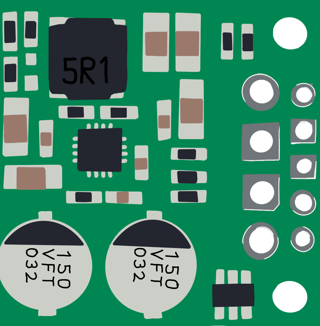
The S13V25F12 is a versatile and efficient voltage regulator capable of both stepping up and stepping down input voltages to provide a stable output voltage. This component is designed by Pololu and is ideal for a wide range of electronic applications where the input voltage can vary, but a constant output voltage is required.
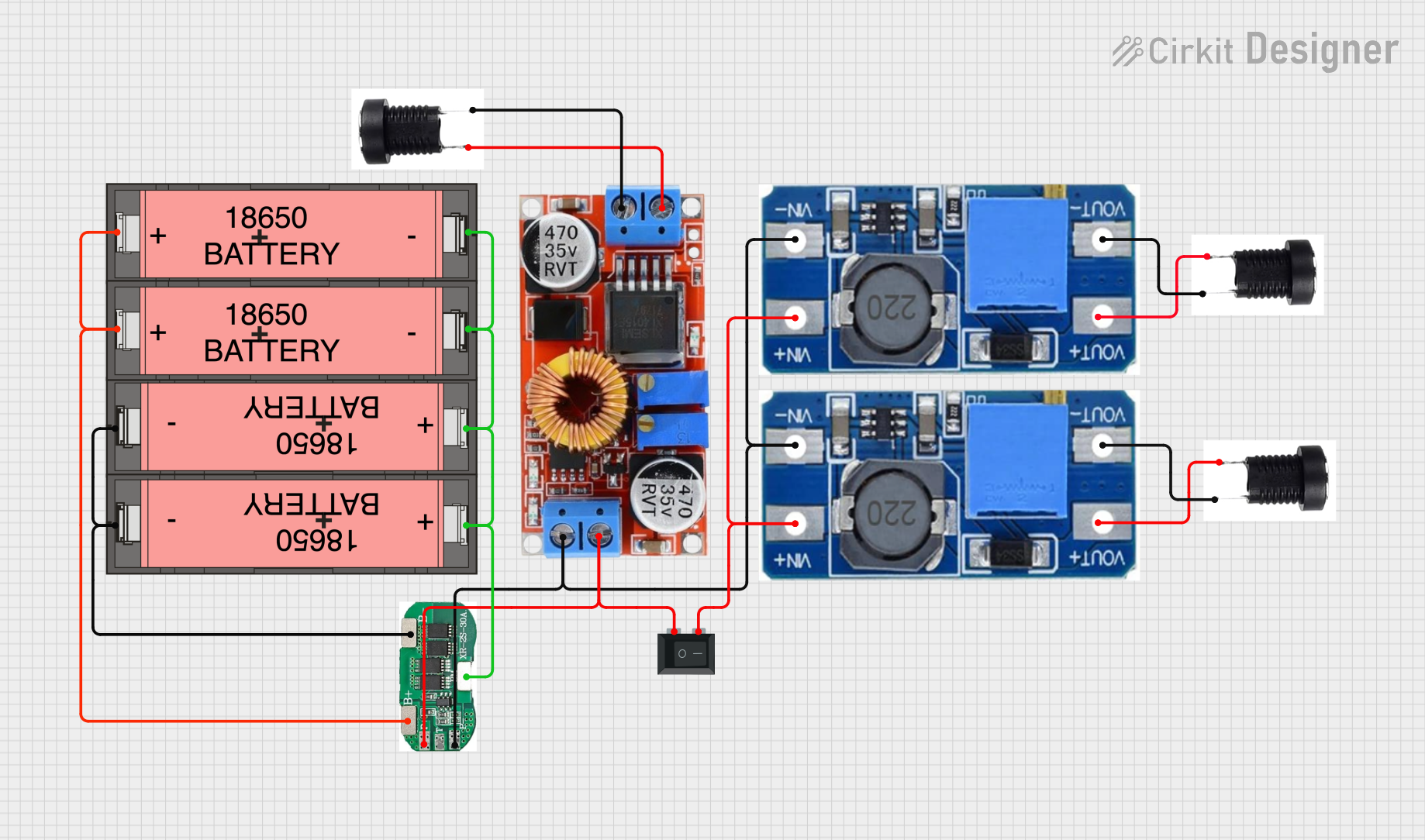
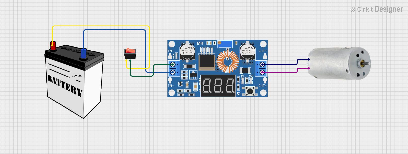
Explore Projects Built with S13V25F12 Step Up/Down Voltage Regulator

 Open Project in Cirkit Designer
 Open Project in Cirkit Designer
 Open Project in Cirkit Designer
 Open Project in Cirkit Designer
Explore Projects Built with S13V25F12 Step Up/Down Voltage Regulator

 Open Project in Cirkit Designer
 Open Project in Cirkit Designer
 Open Project in Cirkit Designer
 Open Project in Cirkit Designer
Common Applications and Use Cases
- Battery-powered devices where the battery voltage can fall below or rise above the desired voltage for the electronics.
- Power supply for sensors or microcontrollers with specific voltage requirements.
- Portable electronics that need to maintain a stable voltage despite varying power sources.
Technical Specifications
Key Technical Details
- Input Voltage Range: 2.9V to 12V
- Output Voltage Range: 1.25V to 13.8V
- Output Current: Up to 2A with adequate cooling
- Efficiency: 80-90% typical for many combinations of input voltage, output voltage, and load
- Quiescent Current: <1mA
Pin Configuration and Descriptions
| Pin Number | Name | Description |
|---|---|---|
| 1 | VIN | Input voltage (2.9V to 12V) |
| 2 | GND | Ground connection |
| 3 | VOUT | Regulated output voltage (1.25V to 13.8V) |
| 4 | FB | Feedback pin for setting output voltage |
| 5 | EN | Enable pin for turning the regulator on/off |
Usage Instructions
How to Use the Component in a Circuit
Connecting Input Power: Connect the input power source to the VIN and GND pins. Ensure that the input voltage is within the specified range of 2.9V to 12V.
Setting Output Voltage: The output voltage can be set by adjusting the voltage divider connected to the FB pin. Refer to the Pololu datasheet for the appropriate resistor values to achieve the desired output voltage.
Enabling the Regulator: The EN pin can be left floating to enable the regulator by default. Alternatively, it can be driven high (to VIN) to enable the regulator or driven low (to GND) to disable it.
Connecting the Load: Connect the load to the VOUT and GND pins. Ensure that the load does not exceed the maximum current rating of the regulator.
Important Considerations and Best Practices
Heat Dissipation: Ensure adequate cooling for the regulator, especially when drawing high currents or when there is a significant difference between input and output voltages.
Capacitors: It is recommended to use input and output capacitors to minimize voltage ripple and improve stability. Refer to the datasheet for recommended values.
Enable Pin: If using the EN pin to control the regulator, ensure that the voltage applied to this pin does not exceed the VIN voltage.
Troubleshooting and FAQs
Common Issues
Output Voltage Fluctuation: Check that the input voltage is stable and within the specified range. Also, verify that the capacitors are correctly installed and of the recommended values.
Regulator Overheating: Ensure that the regulator is not operating above its current rating and that there is sufficient cooling.
Regulator Not Enabling: If using the EN pin, ensure that it is being driven correctly. A floating EN pin should enable the regulator by default.
Solutions and Tips for Troubleshooting
Check Connections: Verify all connections are secure and correct according to the pin configuration.
Measure Voltages: Use a multimeter to measure the input and output voltages to ensure they are within the expected ranges.
Inspect Components: Look for signs of damage or overheating on the regulator and surrounding components.
FAQs
Q: Can I use the S13V25F12 without an external capacitor? A: While the regulator may work without external capacitors, it is strongly recommended to use them for optimal performance and stability.
Q: What should I do if the output voltage is not stable? A: Ensure that the feedback resistors are correctly chosen and installed, and that the input and output capacitors are of the recommended values.
Q: How can I control the EN pin with a microcontroller like an Arduino UNO? A: You can connect the EN pin to a digital output pin on the Arduino and set it HIGH to enable the regulator or LOW to disable it.
Example Arduino Code
// Define the pin connected to the EN pin of the regulator
const int enablePin = 7;

void setup() {
  pinMode(enablePin, OUTPUT);
  // Start with the regulator enabled
  digitalWrite(enablePin, HIGH);
}

void loop() {
  // Code to control the regulator enable state
  // For example, to turn off the regulator:
  digitalWrite(enablePin, LOW);
  // Add a delay or additional code as needed
  // To turn the regulator back on:
  digitalWrite(enablePin, HIGH);
}
Note: The above code is a simple example of how to control the S13V25F12 voltage regulator's enable pin using an Arduino UNO. Adjust the code as necessary for your specific application.